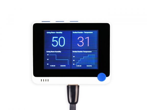
Wio Terminal for RPi From Seeed Studio (Source 01)
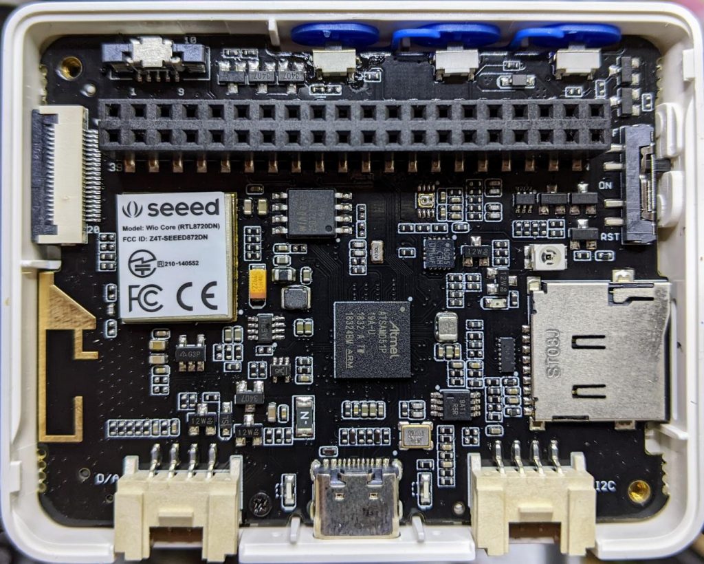
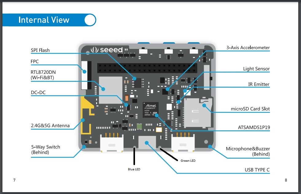
Inside the hard-to-open Wio Terminal

|
Click on the photo to enlarge it.
Wio Terminal for RPi From Seeed Studio (Source 01) |
Click on the photo to enlarge it. Inside the hard-to-open Wio Terminal |
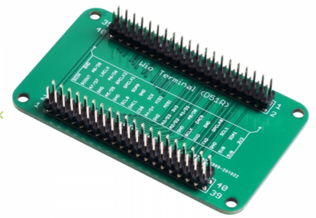
The Adapter Board SKU A1716470 from Seeed Studio (Source 01), shown above, can
be used to convert the Wio Terminal's 40 pin female GPIO into a 40 pin male
GPIO that is normally found on a Raspberry Pi.  This Adapter Board works fine
as a 40-pin GPIO extender on a Raspberry Pi, but only if one male header is
replaced by a female header (by soldering).  This adapter was designed to
permit one of the various RPi hats to be connected to the Wio Terminal which
has a female 40 pin GPIO interface (unlike the male 40-pin GPIO connector
on every Raspberry Pi).  The user can optionally use this male-male
Adapter Board with a female-female 40 conductor cable to make a longer
40 conductor male-female extender cable.

The Wio Terminal Chassis - Battery, mentioned below, has both male and female 40-pin
GPIO connectors.  It can also be used as a small GPIO extension between the
Wio Terminal and the many "hats" available for the Raspberry Pi when programs are
run by the microprocessor in the Wio Terminal.  This Wio Terminal Chassis is exactly
the same size as the Wio Terminal. It can be seen briefly (but is not mentioned)
in Video Source 08. Look for "Gaming with Wio Terminal".

When using a Pi-400, two tiny 90 degree 40-pin connector extenders can be used
to attach the Wio Teminal as a peripheral to the RPi.  But the image will be
inverted, so you will need to stand on your head while typing. LOL
Wio Terminal CC-BY-SA Pages

1 Version Control (version 1)
2 ATSAMD51P19A (& uSD card & blue 90D LED)
3 Power
4 Buzzer & MIC
5 Header Interface and Button (& Light Sensor
   & Groves & IR & FPC & TSAMD51P19A Download)
6 WiFi+BLE ( & Input Current 600 mA control)
7 Gyroscope & LCD (uses I2C Address 0x19)
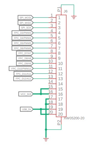
FPC connector pins (probably for an OV7670 camera)

 1 SPI MOSI        11 FPC D10/PWM10
 2 SPI MISO        12 FPC D11/A11
 3 SPI SCK         13 FPC D12/A12
 4 FPC D3/PWM3     14 na
 5 FPC D4/PWM4     15 VCC 3V3
 6 FPC D5/PWM5     16 VCC 3V3
 7 FPC D6/PWM6     17 GND
 8 FPC D7/A7       18 GND
 9 FPC D8/A8       19 USB 5V
10 FPC D9/A9       20 USB 5V
Wio Terminal FPC header and Camera
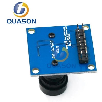
Baozhu [of seeed studio]
Aug '20
Haha, we are developing a corresponding camera.We also have tinyCV for users, please check out our website.

derekmulcahy
Aug '20
A bit of investigation and I think an OV7670 will work on the 13 pins available on the FPC connector. HREF
can be left unconnected and RESET and PWDN can be tied high and low respectively. I have one of those cameras
on a breakout board. I think the camera could also hang off the Raspberry Pi connector as well.

Adafruit are developing a library using that camera attached to a SAMD51 board but it uses the MCUs Parallel
Capture Controller and the dedicated pins have other/better uses on the WIO Terminal.

So it looks like I can make progress. My real goal is to use color output from a 32x24 MLX90640 IR camera
as an overlay on top of a grayscale camera image. The frame rates won’t be fantastic but it should look pretty.

Reply

Baozhu [of seeed studio]
Aug '20
The hardware connection is fine, we already have some prototypes.
Source 17 contains more references to the ov7670 camera which can cost as little as US $1.58 from Quason at Ali Express. Click on the photo to enlarge it.
Click on the photo to enlarge it.
 Wio Terminal Chassis - Battery |
Click on the photo to enlarge it.
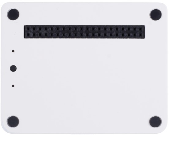 Wio Terminal Chassis - Battery (back view) |
Specifications
Item Detail
Power Supply 4.75V - 5.25V
Built-in battery 650mAh
On/Off Button "Off" puts it in sleep mode [located on the back between the 2 leds]
Charging current Max: 660mA
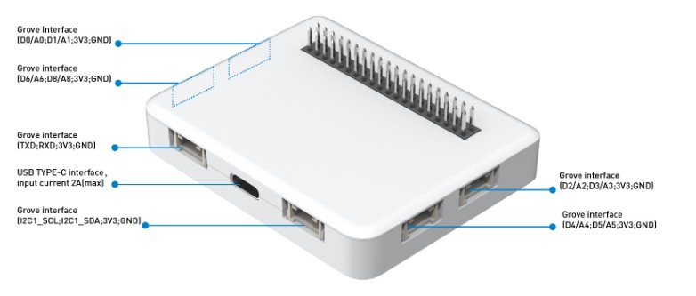
Grove Interface Grove Analog/Digital * 4, Grove I2C * 1, Grove UART * 1
GPIO Interfaces 2 40 pin (male and female) headers pass through
Green,Red & Yellow LEDs indicates charging, discharging etc (located on back)
yellow LED has probably deep deprecated
Magnets Included To attach to metal cabinets
OverCurrent protection Included
USB Type-c Charging Connector is at center of the bottom edge
Hiccup mode Hiccup Protection [??]
[New version] Chassis - Battery board LED modes:
Green LED: Light On means the Wio Terminal board is charging.
On/Off pushbutton: press to toggle power to the attached Wio Terminal
Red LED: Light on means the OTG (battery discharge) is enabled.
Yellow LED: Light on means the male interface output/input is 5V [probably deprecated].
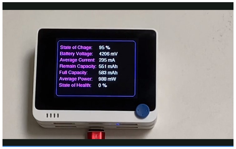
A newer version of the Wio Terminal Chassis - Battery (Source 39 ) adds an On/Off button
[perhaps replacing the Yellow LED in the center bottom edge] and a "fuel gauge" (using
an internal TI BQ27441) that is displayed on the LCD of the Wio Terminal (see video
[while discharging and charging] at Source 39). Source 39 also has a very short video
showing the dynamic fuel gauge, its schematic and includes a C/C++ program. There is a
minor controversy (eg by genebren in Source 39 ) about the validity of the "fuel" values
that are displayed. Apparently, the I2C connection required for the "Fuel Gauge" is via
the "common" GPIO pins", not via a Grove connector. For the code that produces the status
display that appears below, refer to Source 13 in Article 189.
Click on the photo to enlarge it.
Green & Yellow/Red Leds: Precautions

If the battery is unattached to anything, the chassis switches to failure mode,
and the green light blinks at a frequency of 1Hz [once per second].  Please press the
push-button (located between the green and red LEDs). To let the chassis enter sleep mode
for safety consideration, and the LED on the backside of the chassis will go off.
[Presumably, this is necessary to remove all power from the male GPIO pins and
Grove connectors].  [The author of this web-page does not own an early version of the
Wio Terminal Chassis, therefore cannot fully compare the tweo versions.]

On the Seeed Studio website, under LEARN AND DOCUMENTS, the
"[Wiki] Wio Terminal Chassis - Battery (650mAh)" web link
takes you nowhere. Doh?
Source 03 is the Wio Terminal Classroom. Many video "lectures" are provided including (as of 2023CMar12):
Wio Terminal Classroom #1 Hello World
Wio Terminal Classroom #2 Drawing Shapes on LCD
Wio Terminal Classroom #3 Displaying Fonts
Wio Terminal Classroom #4 Displaying Images and simple UI
Wio Terminal Classroom #5 Line Charts and Histograms
Wio Terminal Classroom #6 Using Grove Modules
Wio Terminal Classroom #7 Communication Protocols
Wio Terminal Classroom #8 Built-in Hardware Sensors Part 1
3-way buttons and 5 way switch
Wio Terminal Classroom #9 Built-in Hardware Sensors Part 2
Microphone & Buzzer
Wio Terminal Classroom #10 Built-in Hardware Sensors Part 3
Accelerometer and Light Sensor
Wio Terminal Classroom #11 Build a TV Remote using the built-in IR Emitter
Wio Terminal Classroom #12 Smart Garden Project using Wio Terminal
Wio Terminal Classroom #13 Use Wio Terminal as a Mouse for PC
Wio Terminal Classroom #14 Use Wio Terminal as a Keyboard for a PC
Wio Terminal Classroom with ArduPy #1 Getting Started with Ardupy
Wio Terminal Classroom with ArduPy #2 Fun with LCD
Wio Terminal Classroom with ArduPy #3 Decibel Meter using built-in Microphone
Wio Terminal Classroom with ArduPy #4 Musical Keyboard with built-in Mic
Wio Terminal Classroom with ArduPy #5 AIP [Application Infrastructure Provider] usage and Ardupy Libraries
Wio Terminal Classroom with ArduPy #6 How to write an ArduPy Library
Wio Terminal Classroom with IoT: lessons #1 through #7
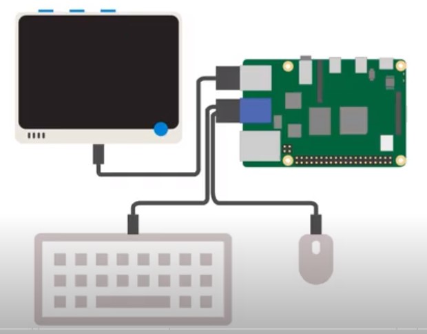
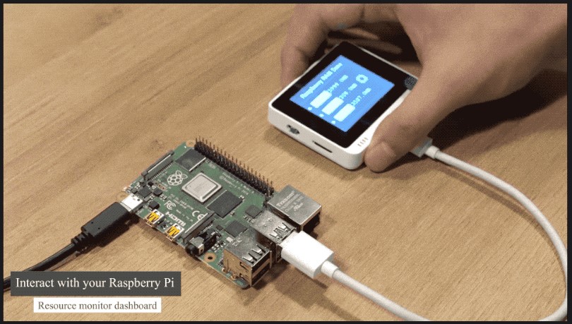
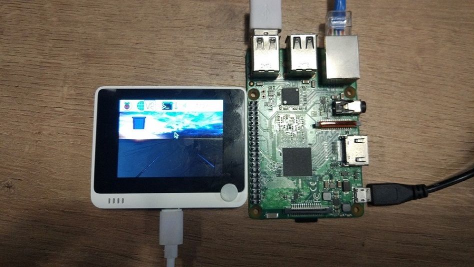
Wio Terminal HMI Display for Raspberry Pi
Built-In Hardware/Sensors Part 1
Built-In Hardware/Sensors Part 2
Built-In Hardware/Sensors Part 3
Communication Protocols
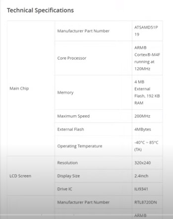
Perhaps the most notable for a Raspberry Pi user might be the "Wio Terminal HMI Display for Raspberry Pi." This display
is indeed tiny (320x240) but it will be sufficient for many projects.
Click on the photo to enlarge it.
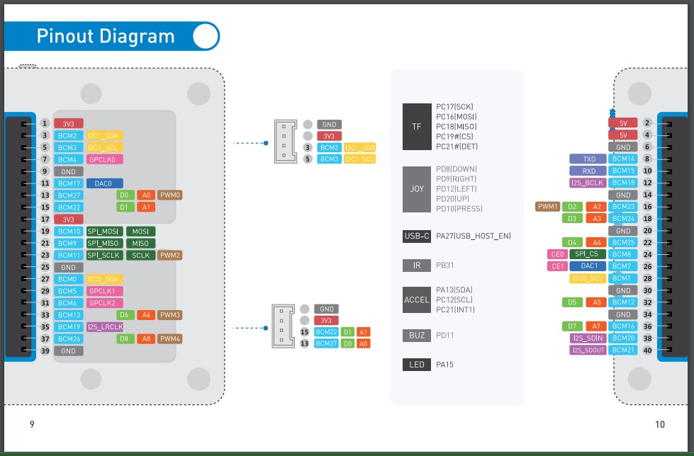 Wio Rpi 40 GPIO Pinouts |
Click on the photo to enlarge it.
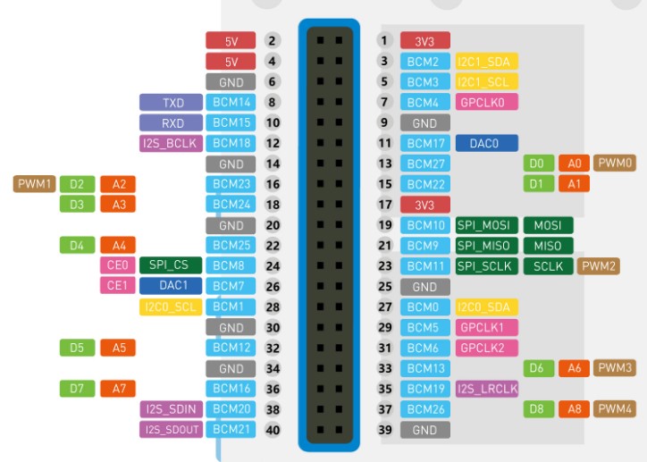 Wio Rpi 40 GPIO Pinouts (familiar layout) |
functions to access info:
-set up serial port
-acquire CPU temperature
-acquire RAM info
-acquire % of CPU used
-acquire disk space info
main program:
-getCPUtemperature()
-getCPUuse()
-getDisk info
# RpiSystemStatusOnWio.py
# Source: https://wiki.seeedstudio.com/Wio-Terminal-Reading-Raspberry-Pi/

import os
import time
import serial

# Settings for reading from Arduino Serial
serialPort= "/dev/ttyACM0" #Change it to your Serial Port, Check in Arduino IDE !!!
baudRate = 115200
ser = serial.Serial(serialPort, baudRate, timeout=0.5)
time.sleep(2)

# Return CPU temperature as a character string
def getCPUtemperature():
    res = os.popen('vcgencmd measure_temp').readline()
    return(res.replace("temp=","").replace("'C\n",""))

# Return RAM information (unit=kb) in a list
# Index 0: total RAM
# Index 1: used RAM
# Index 2: free RAM
def getRAMinfo():
    p = os.popen('free')
    i = 0
    while 1:
        i = i + 1
        line = p.readline()
        if i==2:
            return(line.split()[1:4])

# Return % of CPU used by user as a character string
def getCPUuse():
    return(str(os.popen("top -n1 | awk '/Cpu\(s\):/ {print $2}'").readline().strip()))

# Return information about disk space as a list (unit included)
# Index 0: total disk space
# Index 1: used disk space
# Index 2: remaining disk space
# Index 3: percentage of disk used
def getDiskSpace():
    p = os.popen("df -h /")
    i = 0
    while 1:
        i = i +1
        line = p.readline()
        if i==2:
            return(line.split()[1:5])

def main():
    while True:
        # CPU informatiom
        CPU_temp = getCPUtemperature()
        CPU_usage = getCPUuse()

        # RAM information
        # Output is in kb, here I convert it in Mb for readability
        RAM_stats = getRAMinfo()
        RAM_total = str(round(int(RAM_stats[0]) / 1000,1))
        RAM_used = str(round(int(RAM_stats[1]) / 1000,1))
        RAM_free = str(round(int(RAM_stats[2]) / 1000,1))

        # Disk information
        DISK_stats = getDiskSpace()
        DISK_total = DISK_stats[0]
        DISK_used = DISK_stats[1]
        DISK_perc = DISK_stats[3]

        temp=ser.write(str.encode(CPU_temp+' '+CPU_usage))

        data=ser.write(str.encode(CPU_temp+':'+CPU_usage+':'+RAM_total+':'+RAM_used+':'+RAM_free+':'+DISK_total+':'+DISK_used+':'+DISK_perc))
        ser.flush()
        time.sleep(2)

        print('')
        print('CPU Temperature = '+CPU_temp)
        print('CPU Use = '+CPU_usage)
        print('')
        print('RAM Total = '+str(RAM_total)+' MB')
        print('RAM Used = '+str(RAM_used)+' MB')
        print('RAM Free = '+str(RAM_free)+' MB')
        print('')
        print('DISK Total Space = '+str(DISK_total)+'B')
        print('DISK Used Space = '+str(DISK_used)+'B')
        print('DISK Used Percentage = '+str(DISK_perc))


if __name__ == '__main__':
    try:
        main()
    except KeyboardInterrupt:
        if ser != None:
            ser.close()
#/RpiSystemStatusOnWio.py
#Wio-Terminal-LED.py
# MicroPython / Seeed Wio Terminal / SAMD51
# Wio-Terminal-LED.py - blink the internal blue LED
# scruss, 2022-10
# -*- coding: utf-8 -*-

from machine import Pin
from time import sleep_ms

led = Pin("LED_BLUE", Pin.OUT)  # or Pin(15) or Pin("PA15")

try:
    while True:
        led.value(not led.value())
        sleep_ms(1200)
except:
    led.value(0)  # turn it off if user quits
    exit()
#/Wio-Terminal-LED.py
Micro Python is not delivered with the Wio Terminal.  However work is in progress to this end.  For this to work, a mechanism
is needed to flash Micro Python to the Wio Terminal.  An uptodate version of MicroPython is needed.  A Micro-Python editor is
needed for the Wio Terminal.  A user is needed to write code in MicroPython and run it on the Wio Terminal.  The following
work is in progress:

"scruss" has written some Micro Python code which will make use of the peripherals built into the Wio Terminal.
     Sources 18 links to his work
     "scruss" also describes how to install Micro Python on the Wio Terminal
"robert-hh" has created a MicroPython Editor that runs on the Wio Terminal (Sources 19 & 20)
"peterhinch" is creating a MicroPython Flash memory driver for the Wio Terminal (Source 21)
The following comment by scruss summarizes all of this as follows:
USB-C, Display, Grove, WiFi, BLE, SDCardSource 23 also shows the source code at Github, the latest release and the nightly builds by Seeed Studio. Github article "MicroPython on the Seeed Wio Terminal" (Source 20) contains many references to information about MicroPython on the Wio Terminal.
(by the author:D@CC on 2023CMar15)
1. Turn OFF (up position away from USB connector) the Wio Terminal on/off switch.
2. Connect Wio Terminal USB cable to any USB power source (not a computer USB).
  The LCD on front of the Wio Terminal will display
  "PUSH [top] LEFT BUTTON TO CONTINUE" with a game (image below)
  Also a Green Led will light up on the back (and bottom edge) of the Wio Terminal
  This indicates that the Wio Terminal is probably functional.
Click on the photo to enlarge it.
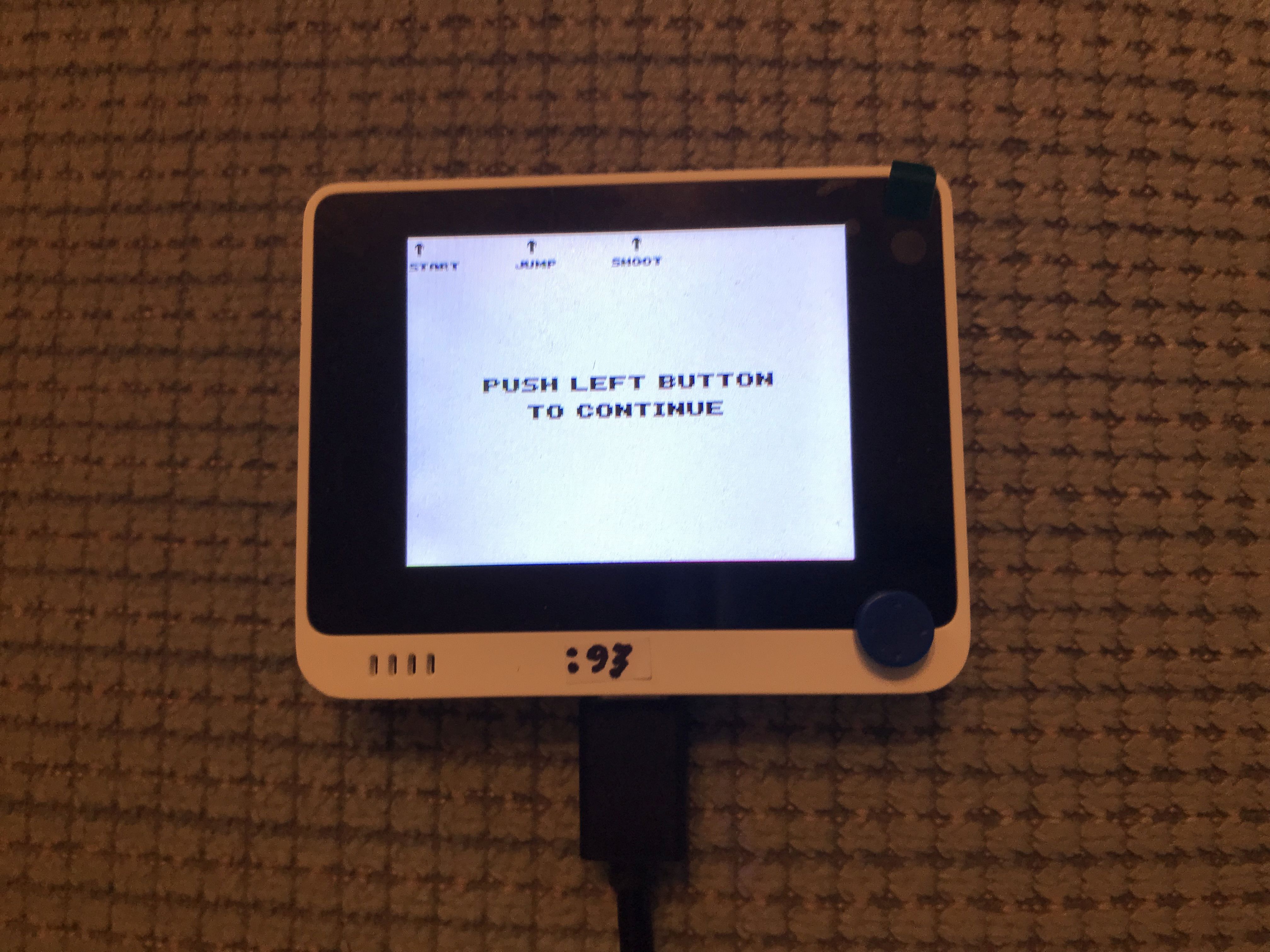
3. Use the top 3 buttons (LEFT, MIDDLE, RIGHT) to play the game.
4. To exit from the game, unplug from the USB power source
  The LCD display on the Wio Terminal will go dark.
  Also the Green Led will turn OFF on the back of the Wio Terminal
5. Turn OFF (up position)) the Wio Terminal on/off switch.
6. Connect the Wio Terminal USB cable to an any Laptop (eg HP) USB connector.
7. Turn ON (middle position) the Wio On/Off switch.
  On the back of the Wio Terminal, the Green LED turned ON
8. Turn OFF the Wio On/Off switch
  Green LED turned OFF
9. Turn ON (middle position) the Wio On/Off switch.
  The LCD on front of the Wio Terminal will display the game again:
  "PUSH LEFT BUTTON TO CONTINUE"
  Also a Green Led will light up on the back of the Wio Terminal
  There should be no sign of the Wio Terminal,
  ie no drive volume on the laptop monitor.
	[optional voltage test in steps 10 to 12]
	10. On the back of the Wio Terminal, pin 01 is in the bottom right corner
	   of the GPIO connector ( when "seeed" is not upside down).
	11. Hook a Red LED through a 150 ohm resistor between GPIO pins 1 & 6
	  (which should be 3V3. )
	  The Red LED might light up, indicating 3v3 power present on the GPIO pins
	  If it doesn't light up, change the polarity of the Red LED.
	  If it still doesn't light up, redo all the above steps.
	  This lit Red LED shows that power exists on the Wio Terminal GPIO pins.
	12. Disconnect both wires to the red LED.
13. Quickly double-click (down position twice) the Wio On/Off switch.
  The laptop will (make beeps and) show a USB drive on the
  bottom line of the laptop's display.
14. Click on the "new" USB drive's icon
  It will say
  "Eject Wio Terminal"
   " - Eject Arduino (F:)"
   (A different letter than F: might appear instead.)
15. Using Windows File Explorer, locate drive F: named "Arduino"
16. View the contents of drive F:
  The volume folder contents should be something like:
    CURRENT.UF2
    INDEX.HTM
    INFO_UF2.TXT
  The Wio Terminal game is in the firmware which is the file
  named CURRENT.UF2 (Source 26 as of 2023CMar15).
  (I believe that only 1 file with an extension of "UF2"
  need exist in the first folder of the Wio Terminal.
  Unknown results are possible if more than 1 "UF2" file exists.)
17 Edit (to view but not alter) the file named "INFO_UF2.TXT"
  On a new unused Wio Terminal, (as of 2023CMar15) it will be:
    UF2 Bootloader v3.7.0-79-gd73dd64 SFHWRO
    Model: Wio Terminal
    Board-ID: SAMD51P19A-WioTerminal-v0
18. Close all programs that are using drive F:
19. Click on "Eject Wio Terminal"
20. Unplug the Wio Terminal from the USB connector on the laptop.

CONCLUSION: The Wio Terminal seems to be functioning correctly
1. Begin with a new Wio Terminal.
2. Double-click to put the Wio Terminal into Flash Drive Mode (F: on my laptop).
3. Backup the following 3 files from F: to a folder on the laptop:
           CURRENT.UF2
           INDEX.HTM
           INFO_UF2.TXT
4. Delete the 3 files from the F: drive.
5. Copy only the CURRENT.UF2 file from the backup to the F: drive.
    I see the file being copied. It takes a few seconds.
    When done copying the single file, the Wio Terminal exits flash drive mode.
    The Laptop no longer sees the F: drive.
    The Wio Terminal starts running the game.
        It is as if the UF2 file were placed into a bios to be used for rebooting and
        then the Wio Terminal underwent Power Off then Power On automatically.
    If I again put the Wio Terminal into Flash Drive Mode,
         all 3 files are in the F: drive even though I only copied 1 File
        It appears that when the UF2 file was copied (or when the Wio Terminal
            rebooted) the 2 additional files were restored into the Flash Drive F:
Conclusion: I am able to "delete" the 3 files from F: , then reflash CURRENT.UF2
        to Drive F: correctly.  It will "magically" also restore the other 2 files.
Conclusion 2: If I try to Flash a different UF2 file,
        eg "ArduPy_wio_terminal_lastest.uf2"
         It doesn't seem to get put into the bios.
         Perhaps I need to use minicom to access the Wio Terminal with this firmware.
        Doh?
NOTICE: Deleting all files in the Wio Terminal volume named "Arduino" and by
copying Source 26 and Source 27 to the Wio Terminal Flash Drive should restore
it to its 2018LDec24 factory state (except for the unimportant file named INFO_UF2.TXT).
The INDEX.txt downloaded from Source 27 will need to be renamed to INDEX.HTM.
Never restore this flash drive without making a backup of all the current files on the Wio Terminal.from machine import Pin, Map import time LED = Pin(Map.LED_BUILTIN, Pin.OUT) #tiny blue LED on bottom edge while True: LED.on() time.sleep(1) LED.off() time.sleep(1)
An easy tutorial on how to use minicom with the Pico W can be found in the issue of the MagPi magazine at Source 31.>>> sudo apt install minicom >>> minicom -o -D /dev/ttyACM0 The minicom splash screen should appear. Type ctrl-a z to see the minicom command menu. >>> ctrl-a z Hit ESC to exit from any minicom menu. Use ctrl-a z then S then select "ascii" to select RPi files to be uploaded to Wio Terminal.
where username is the actual name of the main user on the C: drive
2. Then I unzipped the zip file into the same directory.
3. Then I ran Arduino IDE.exe (which was the only .exe file in the folder).
      in folder: E:/E/2023/UF2s/WIo Terminal/Windows_Zip
4. It started up a program with the heading:sketchmar16a|Arduibno IDE 2.0.5-nightly-20230316
     which asked me to
       Select Board  (I double-opened the Wio Terminal, then  saw "Unknown COM4"
                      So I selected that one.
       Then it asked me to Select a Board and Port
       I selected PORT: COM4 Serial Port (USB)
       I saw Raspberry Pi but no Wio Terminal. . . Doh???

      and insert code for both setup()
                             and
                               loop()
Ed.Note: I expected it to find the USB where the Wio Terminal was connected.
         I expected it to connect the Wio Terminal to open an editor
         I expected it to be able to run MicroPython code.
Perhaps it was looking for an Arduino board?????
So I don't know what to do at this point.
So I rebooted and reran Arduino IDE.exe
eg Serial port permissions. now as normal user from terminal: $ ls -l /dev/ttyUSB*

Serial port permissions
now as normal user from terminal:

$ ls -l /dev/ttyUSB*

you will get something like:

crw-rw---- 1 root dialout 188, 0 5 apr 23.01 ttyUSB0
The "0" might be a different number, or multiple entries might be returned. In the first case the data we need is "uucp", in the second "dialout" (is the group owner of the file.

Now we just need to add our user to the group:

$ sudo usermod -a -G group-name username

where group-name is the data found before, and username is your linux user name. You will need to log out and in again for this change to take effect. such as:

$ sudo usermod -a -G dialout tengwang
REPL means "Read Evaluate Print Loop"

I finally discovered how to use REPL to execute single MicroPython statements on the Wio Terminal.
Here is how I did it:

I installed minicom on a Raspberry Pi-400.  Then I plugged the Wio Terminal into the RPi using the
USB cable that came with the Wio Terminal.  I had
already flashed ARDUPY onto the Wio Terminal. I had already copied the BlinkBlueLED.py as
main.py on the Wio Terminal, so the LCD was displaying LED ON and LED OFF repeatedly.

On the RPi, I started up a Terminal window,
then typed in

	>>>minicom -o -D /dev/ttyACM0

which started up minicom, with its command line.
Because the Wio Terminal was already running the BlinkBlueLed.py program, I soon
saw LED ON then LED OFF etc in the RPi Terminal window. So I tried CTRL-C

	> CTRL-C

It displayed:

	< TRACEBACK . . . .
	< . . . . .. .
	< Press any key to enter the REPL, Use CTRL-D to reload.

So I hit ENTER

	> Enter

It displayed REPL | 8.0.4 etc

	>>>

So I entered

	>>> print("aaa") Enter

then it printed out (on the WioT LCD and in the Terminal window)

	< aaa

SUCCESS with REPL
Note: As of 2023CMar18, I discovered that REPL would execute multiple MicroPython statements if you typed them on a single line separated by ";" characters. Another way is to preface the indented multiple lines of code with "if True:".
-CTRL-D will reload (rerun) the main.py program.
-UpArrow lists the previous command
-Enter causes REPL to process the command
-LeftArrow/RightArrow and Delete permit editing of the visible command
-Use a semiColon(;) to separate multiple statements on a command line.
-"import os;os.listdir()" will list the top folder's directory.
-"import os;os.uname()"   will list the name/version of the device eg WioTerminal.
-statements terminated by a ":" with cause indentation of the next line
-BS (the BackSpace key) will remove one level of indention
-after removing all indentation, hitting Return will cause execution of the command
-So starting with "if True:" permits a multi-statement program segment to be input.
-hitting TAB will provide a list of suggested phrases to select from.
-CTRL-C will interrupt a running program
-CTRL-E will go into Paste mode
-hitting "_" will paste the results of the previous assignment or function call???
As of 2023CMar18, the following modules can be used:

_asyncio, _bleio, _pixelmap, adafruit_bus_device, adafruit_pixelbuf, aesio, alarm,
analogio, array, atexit, audiobusio, audiocore, audioio, audiomixer, audiomp3,
binascii, bitbangio, bitmaptools, board, builtins, busio, collections, countio,
digitalio, displayio, errno, floppyio, fontio, framebufferio, frequencyio, getpass,
gifio, i2ctarget, json, keypad, math, microcontroller, msgpack, neopixel_write,
nvm, onewireio, os, paralleldisplay, ps2io, pulseio, pwmio, rainbowio, random, re,
rgbmatrix, rotaryio, rtc, samd, sdcardio, select, sharpdisplay, storage, struct,
supervisor, synthio, sys, terminalio, time, touchio, traceback, ulab, usb_cdc,
usb_hid, usb_midi, vectorio, watchdog, zlib

I don't yet know how to program most of them.
>>> import board
>>> dir(board)
Beware: there are slight differences between CircuitPython, CPython, MicroPython and Thonny. I ran a program to make of list of available Pin Names in CPython for Wio Terminal. The names of most of them identify the relevant Wio Terminal peripheral. The author added the second column. The names are shown below:
WioT Available Pins using CPython
by D@CC on 2023CMar18
/Output From: AvailablePinNames.py
/Source: https://learn.adafruit.com/circuitpython-essentials/circuitpython-pins-and-modules

Pin/Device Pin Name	Device [by D@CC]
-------------------	-----     -------------------------
board.A1 board.D1	GPIO pins
board.A2 board.D2
board.A3 board.D3
board.A4 board.D4
board.A5 board.D5
board.A6 board.D6
board.A7 board.D7
board.A8 board.D8
board.BUTTON_1		Push-Buttons
board.BUTTON_2
board.BUTTON_3
board.BUZZER		Buzzer
board.CS		?
board.D10 board.SCL
board.D13 board.LED	LED
board.D9 board.SDA
board.DAC0		ADCs
board.DAC1
board.GYROSCOPE_INT	Gyroscope/Accelerometer
board.GYROSCOPE_SCL
board.GYROSCOPE_SDA
board.I2S_BCLK		I2S
board.I2S_LRCLK
board.I2S_SDIN
board.I2S_SDOUT
board.IR		IR
board.LIGHT		Light Sensor
board.MIC		Microphone
board.MISO		?
board.MOSI
board.RTL_CLK		Real Time Clock
board.RTL_CS
board.RTL_DIR
board.RTL_MISO
board.RTL_MOSI
board.RTL_PWR
board.RTL_READY
board.RTL_RXD
board.RTL_TXD
board.RX		USB Receive
board.SCK
board.SD_CS		uSD ROM slot
board.SD_DET
board.SD_MISO
board.SD_MOSI
board.SD_SCK
board.SWITCH_DOWN	uJoyStick
board.SWITCH_LEFT
board.SWITCH_PRESS
board.SWITCH_RIGHT
board.SWITCH_UP
board.TFT_BACKLIGHT	LCD screen
board.TFT_CS
board.TFT_DC
board.TFT_MISO
board.TFT_MOSI
board.TFT_RESET
board.TFT_SCK
board.TX		USB transmit
/Output: AvailablePinNames.py
/Source: https://learn.adafruit.com/circuitpython-essentials/circuitpython-pins-and-modules
/WioT_AvailablePins.txt
print("for uf2=ArduiPywioterminal_lastest.uf2") import supervisor
supervisor.set_next_code_file(filename="AvailablePinNames.py")
print("On the Wio Terminal, please Turn the Power button OFF then ON")
# this works when CTRL-D is pressed in REPL. But not using Power OFF/ON"
#program:  sdHello.py
import os
from arduino import sdcard
# from machine import Map

SD=sdcard()
# sdcard(64,Map.SPI2,5000000) # equal for Wio Terminal
os.mount(SD,'/sd')

with open('/sd/hello.txt', 'w') as f:
    f.write('Hello world')

print(open('/sd/hello.txt').read())
#Source: https://github.com/Crazyhackelkorn/seeed-ardupy-sdcard
#/sdHello.py
I am mainly interested in controlling the Wio Terminal by a Raspberry Pi using MicroPython code.

I plan to produce the following:

App01 - A library of Raspberry Pi Python functions that "control" many of the components of the Wio Terminal.
App02 - A Grove connector/cable attached to a TMP102 I2C temperature sensor (for my pir2 home controller.
App03 - A microSD RPi boot card named "IX uHDMI" that uses the Wio Terminal as a mini HDMI monitor.
App04 - A microSD RPi boot card named "IX WioT" that demos the capabilities of the Wio Terminal.
App05 - A microSD RPi boot card named "IX Grove" that demos various Grove devices most using the Wio Terminal.
App06 - A microSD RPi boot card named "IX uSD2" that will access a second microSD slot via the Wio Terminal.
App07 - A microSD RPi boot card named "IX menu" mainMenu to select available programs on the Wio Terminal.

 Wio Terminal (1:15 min)
by Seeed Studio
WIO Terminal - Great Development Platform ( Arduino and MicroPython Raspberry Pi) (6:41 min)
by Volos Projects
Wio Terminal Classroom #1 | Hello World (30:09 min)
by Lakshantha of Seeed Studio
FPC (Flexible Printed Circuit) Connector (0:49 min)
by Yokowo
Wio Terminal HMI Display for Raspberry Pi (12:52 min)
by Lakshantha of Seeed Studio
Wio Terminal Hardware Monitor - Wirelessly Monitor ALL Your Devices (21:19 min)
by Raid Owl
MicroPython on a Wio Terminal ( 8:01 min)
by unknown lad from gurgleapps.com
Wio Terminal (1:15 min)
by Seeed Studio
WIO Terminal - Great Development Platform ( Arduino and MicroPython Raspberry Pi) (6:41 min)
by Volos Projects
Wio Terminal Classroom #1 | Hello World (30:09 min)
by Lakshantha of Seeed Studio
FPC (Flexible Printed Circuit) Connector (0:49 min)
by Yokowo
Wio Terminal HMI Display for Raspberry Pi (12:52 min)
by Lakshantha of Seeed Studio
Wio Terminal Hardware Monitor - Wirelessly Monitor ALL Your Devices (21:19 min)
by Raid Owl
MicroPython on a Wio Terminal ( 8:01 min)
by unknown lad from gurgleapps.com Exploring the Wio Terminal ( 1:14 min)
by Seeed Studio in 2021
Seeed Studio (USA) Website
by Seeed Studio
Wio Terminal: for RPi & Arduino (from Seeed Studio)
by Seeed Studio
Wio Terminal Classroom for Arduino
by Lakshantha of Seeed Studio in 2020
Reading Rpi's System Status using a Wio Terminal (with Python code)
by Jianjing Huang of Seeed Studio in Jan 31 2023
Python Code on Raspberry Pi
Exploring the Wio Terminal ( 1:14 min)
by Seeed Studio in 2021
Seeed Studio (USA) Website
by Seeed Studio
Wio Terminal: for RPi & Arduino (from Seeed Studio)
by Seeed Studio
Wio Terminal Classroom for Arduino
by Lakshantha of Seeed Studio in 2020
Reading Rpi's System Status using a Wio Terminal (with Python code)
by Jianjing Huang of Seeed Studio in Jan 31 2023
Python Code on Raspberry Pi by Jianjing Huang of Seeed Studio in Jan 31 2023 (transcriber:D@CC)
Circuit Python on Wio Terminal
byJianjing Huang of Seeed Studio Wiki in Jan 31 2023
by Jianjing Huang of Seeed Studio in Jan 31 2023 (transcriber:D@CC)
Circuit Python on Wio Terminal
byJianjing Huang of Seeed Studio Wiki in Jan 31 2023 Circuit Python on Wio Terminal User Manual (pdf)
D51R by Seeed Studio Wiki in Jan 31 2023
Seeed Studio Wiki Platform includes Wio Terminal>Sensor>Wio Terminal
includes a Wio Terminal Hardware Overview by Seeed Studio Wiki in Jan 31 2023
Seeed Studio Weekly Wiki
by Matthew of Seeed Studio Wiki in Mar 06 2023
Differences between MicroPython & CPython
by github in Mar 11 2023
Wio Terminal Schematic
by Seeed Studio in Mar 11 2023
ATSAMD51N19A Datasheet
by Microchip in Mar 11 2023
Seeed Studio Forum Website
by Seeed Studio
USBDisplayAndMouseControl
by weihong.cai of Seeed Studio (github)
USBDisplayAndMouseControl (c/c++ in zip format)
Circuit Python on Wio Terminal User Manual (pdf)
D51R by Seeed Studio Wiki in Jan 31 2023
Seeed Studio Wiki Platform includes Wio Terminal>Sensor>Wio Terminal
includes a Wio Terminal Hardware Overview by Seeed Studio Wiki in Jan 31 2023
Seeed Studio Weekly Wiki
by Matthew of Seeed Studio Wiki in Mar 06 2023
Differences between MicroPython & CPython
by github in Mar 11 2023
Wio Terminal Schematic
by Seeed Studio in Mar 11 2023
ATSAMD51N19A Datasheet
by Microchip in Mar 11 2023
Seeed Studio Forum Website
by Seeed Studio
USBDisplayAndMouseControl
by weihong.cai of Seeed Studio (github)
USBDisplayAndMouseControl (c/c++ in zip format) by weihong.cai of Seeed Studio (github)
FPC connector for an future OV7670 camera
by derekmulcahy in seeed studio forum in Aug 2020
OV7670 camera references
by Mrarduino in seeed studio forum in Oct 2022
MicroPython on the Seeed Studio Wio Terminal: it works!
by scruss in 2022-11-12
MicroPython Editor (scruss mentions Wio Terminal use)
by robert-hh (Robert Hammelrath) at github in 2023/3/13
samd51: MicroPython on the Seeed Wio Terminal
by robert-hh (Robert Hammelrath) at github in 2022/Nov/04
A MicroPython Flash memory driver
by peterhinch at github in 2022/Dec/13
Getting Started with MicroPython on the Raspberry Pi Pico
Presentation by Stewart Russell (scruss @ scruss.com) in 2021-02-11
Wio Terminal MicroPython Firmware Image (uf2)
nightly rebuild by seeed studio on 2023CMar13
Ham Radio and Linux "Talk at 31 1/4 bps!"
Presentation by Stewart Russell (scruss @ scruss.com VA3PID) in 2011GAug09
Installing Circuit Python by Adafruit on 2023CMar15
original Wio Terminal game (uf2)
CURRENT.UF2 by seeed studio on 2023CMar15
original Wio Terminal game (INDEX.txt)
INDEX.HTM by seeed studio on 2023CMar15
MicroPython & ArduPy On Wio Terminal
By gurgleapps on 2023CMar15
wiki.seeedstudio.com/ArduPy
By gurgleapps on 2023CMar16
Setting up Your Wio Terminal
By Mithru Vigneshwara on 2023CMar19
MagPi magazine 119 pp34-41 (PDF)
by Lucy Hattersley at MagPi Magazine c2022 F Jun 30
Pi: Tiny2040 & Pico W (175.html)
by David Cole at 2022 G Jul 09
wio.cli: Command Line for Wio Terminal - GitHub
by awong1900 at 2016MDec13
ArduPy on the Wio Terminal (for MicroPython)
by Stephen Smith at 2021ISep12
Circuit Python Documentation
Release 8.1.0-beta.0 by CPython Contributors at 2023CMar17
Circuit Python Available Pin Name
by learn.adafruit.com on 2023CMar17
Wio Terminal Chassis - Battery
by Seeed Studio on 2023CMar17
Reading/Writing from the SD Card
by Seeed Studio on 2023CMar20
Wio Terminal - Battery Fuel Gauge
by element14 on 8 Jan 2021
Seeed Studio Forum (needs userid)
by Seeed Studio on 2023CMar20
WioIXkb : Wio Interface without KeyBoard (187.html)
by D@CC on 2023CMar21
erase the flash on the Wio Terminal
by laksham (Seeed Forum) on 2020MDec
by weihong.cai of Seeed Studio (github)
FPC connector for an future OV7670 camera
by derekmulcahy in seeed studio forum in Aug 2020
OV7670 camera references
by Mrarduino in seeed studio forum in Oct 2022
MicroPython on the Seeed Studio Wio Terminal: it works!
by scruss in 2022-11-12
MicroPython Editor (scruss mentions Wio Terminal use)
by robert-hh (Robert Hammelrath) at github in 2023/3/13
samd51: MicroPython on the Seeed Wio Terminal
by robert-hh (Robert Hammelrath) at github in 2022/Nov/04
A MicroPython Flash memory driver
by peterhinch at github in 2022/Dec/13
Getting Started with MicroPython on the Raspberry Pi Pico
Presentation by Stewart Russell (scruss @ scruss.com) in 2021-02-11
Wio Terminal MicroPython Firmware Image (uf2)
nightly rebuild by seeed studio on 2023CMar13
Ham Radio and Linux "Talk at 31 1/4 bps!"
Presentation by Stewart Russell (scruss @ scruss.com VA3PID) in 2011GAug09
Installing Circuit Python by Adafruit on 2023CMar15
original Wio Terminal game (uf2)
CURRENT.UF2 by seeed studio on 2023CMar15
original Wio Terminal game (INDEX.txt)
INDEX.HTM by seeed studio on 2023CMar15
MicroPython & ArduPy On Wio Terminal
By gurgleapps on 2023CMar15
wiki.seeedstudio.com/ArduPy
By gurgleapps on 2023CMar16
Setting up Your Wio Terminal
By Mithru Vigneshwara on 2023CMar19
MagPi magazine 119 pp34-41 (PDF)
by Lucy Hattersley at MagPi Magazine c2022 F Jun 30
Pi: Tiny2040 & Pico W (175.html)
by David Cole at 2022 G Jul 09
wio.cli: Command Line for Wio Terminal - GitHub
by awong1900 at 2016MDec13
ArduPy on the Wio Terminal (for MicroPython)
by Stephen Smith at 2021ISep12
Circuit Python Documentation
Release 8.1.0-beta.0 by CPython Contributors at 2023CMar17
Circuit Python Available Pin Name
by learn.adafruit.com on 2023CMar17
Wio Terminal Chassis - Battery
by Seeed Studio on 2023CMar17
Reading/Writing from the SD Card
by Seeed Studio on 2023CMar20
Wio Terminal - Battery Fuel Gauge
by element14 on 8 Jan 2021
Seeed Studio Forum (needs userid)
by Seeed Studio on 2023CMar20
WioIXkb : Wio Interface without KeyBoard (187.html)
by D@CC on 2023CMar21
erase the flash on the Wio Terminal
by laksham (Seeed Forum) on 2020MDec