139 A&C: PiR2A Area Controller Prototype (139.html)
Keywords: A&C PiR² PiR2A Area Controller MIC MehInCharge "Meh In Charge" I2C HC "HC logic" Raspberry Pi D@CC ICH180R2 Upton RDC
In late April of 2020, the first prototype of the PiR2 Area Controller was created by the author. The component count of the PiR2A is only 11. These 11 components (1 tiny IC board, 7 resistors, 2 LEDs and a button) constitute the complete PiR2A prototype. The software driving it is an on-going development project. It is not necessary to purchase any additional software to run the PiR2A. (The Linux and python software components used are all free.) A diagram of a house with two full PiR2A systems appears later in this article. A single TV monitor, keyboard and mouse are useful when setting up the PiR2A, but can be soon removed. Each PiR2A can be operated remotely using a Windows, Apple or Linux laptop connected to a common router. For example, this can be done using the existing RDC (Remote Desktop Connection) software that ships with Microsoft Windows 10. The Remote Desktop Connection software can be found listed under "Windows Accessories".
(To enlarge .....Click it.)
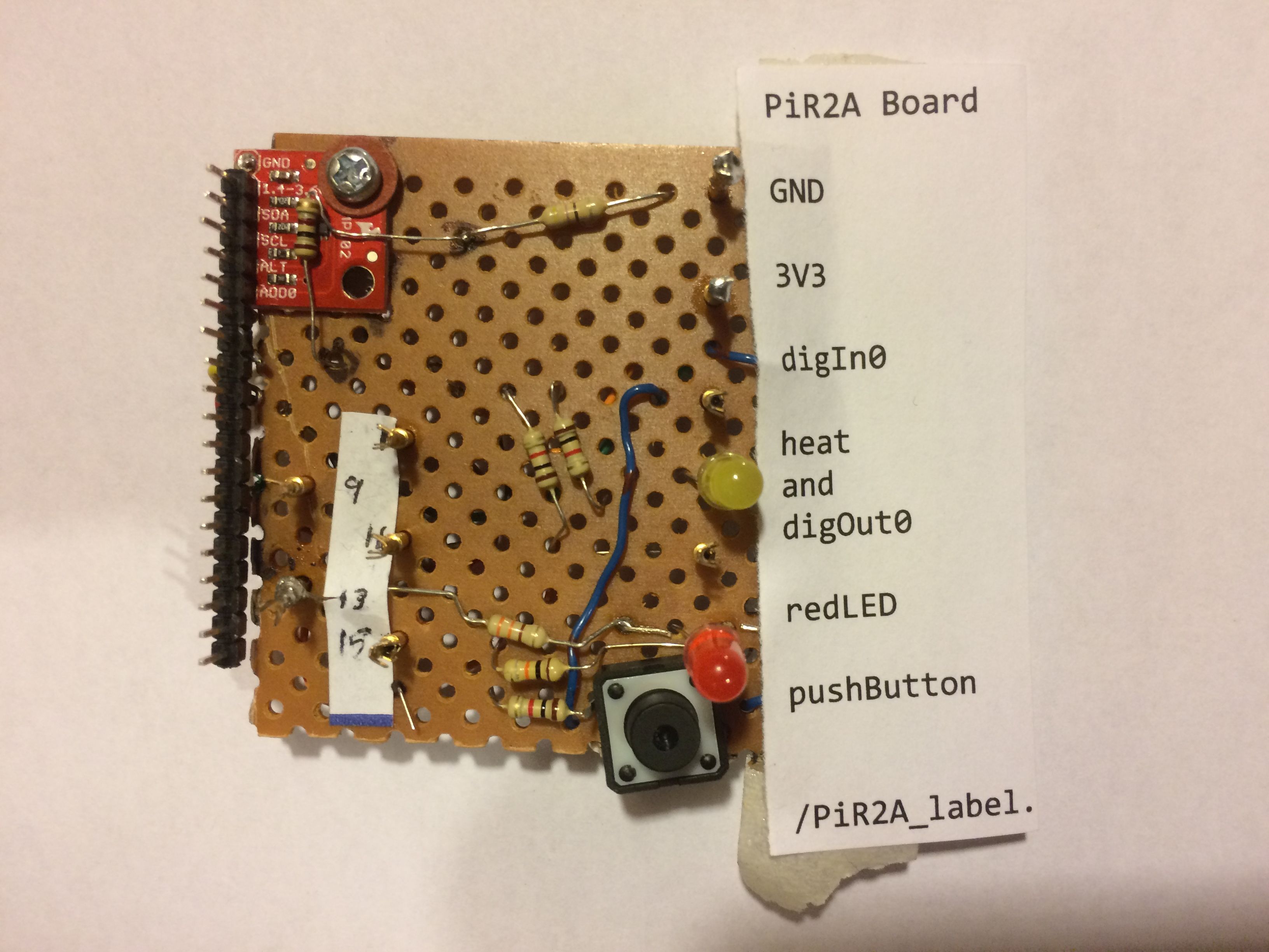
The first PiR2A Prototype
A combination schematic/physical drawing of the PiR2A circuit can be found in Source 03 at the end of this article. As seen in the photo above, (as of 2020 E May) this prototype of the PiR2 CONTROLLER provides the following Operational External IO Devices:
Operational External IO Devices (on the PiR2A)
- digIn0 - one bit of digital input
- digOut0 - one bit of digital output.
This line also turns on the yellow LED, and
optionally the "heat" resistor described below.
- pushButton - a button that the operator can press.
This pushbutton is connected to the digIn0 line.
- redLED - a red LED (visual lamp)
- tempId00 - a thermometer that reads the nearby area temperature (I2C)
Refer to Source 06 below for more information about the I2C bus.
Operational Internal IO Devices (on the Raspberry Pi)
- procTemp - analog temperature of internal processor of the Raspberry Pi
- toOwner - messages to the Owner (from the PiR2 software)
- fromOwner - commands from the Owner
- audioTV - audio message "channel" to the TV
- piIP - IP address (read only) of the Raspberry Pi on the house's router
- piOS - the name (read only) and vsn of the operating system running on the Raspberry Pi
e.g. "Linux raspberrypi 4.14.98-v7+"
- piSN - serial number (read only) of the Raspberry Pi
- logA - manual log entries (readable/writable)
- imageTV - photo image "channel" to the TV
- piArea - name of area being controlled (readable/writeable)
The Operational Internal IO Devices listed immediately above are operational whether or not the PiR2A is installed. Some of them are necessary for the operation of the PiR2 controller. Others facilitate communication with the operator. The fromOwner virtual device permits the owner to issue commands to the PiR2 software. Some of these commands acquire information from the IO Devices on the PiR2. Other commands control the IO Devices. The fromOwner virtual IO device accepts input in 3 different ways:
- from the owner while the PiR2 is starting up
- written messages to the latent command log while the operator is logged into the MIC site (described below)
- in real time via the SEND button on the future PiR2 console panel.
Detailed Descriptions of some IO Devices
All but the tempId00 are very straightforward and require almost no explanation. Each is represented by one bit of information. The tempId00 thermometer is tiny like the other ioDevices. But it is more complex because it is a single IC chip that communicates with the computer using I2C and its two serial data lines (SDA and SCL). The computer used is any model of the Raspberry Pi, which has a male connector block allowing for up to 40 electrical pins to be used. The US$5 Raspberry Pi model Zero (Source 05) can probably be used with the PiR2A although this has not been tested. However, I have successfully used the Pi model Zero for other purposes. One drawback of the model Zero is that some GPIO pins would need to be soldered to the model zero computer board. The PiR2 controller uses the lowest numbered physical pins. The PiR2A prototype is attached to the Raspberry Pi using a standard 2x20 female-female ribbon cable.
The tempId00 IO Device
The tempId00 thermometer uses a Texas Instruments (ti) TMP102 IC chip. This very very tiny black chip is located near the center of the (1 cm x 1 cm) red circuit board in the top left corner of the PiR2A prototype shown above. The data lines of the chip are compatible with the +3.3 volt power and the HC logic family (as is the Raspberry Pi). The HC (High voltage, Complementary) logic family has a very wide supply voltage range, has good noise immunity, plenty of speed and its many different logic gates are widely available. The tempId00 ioDevice is very sophisticated in that it reads the temperature using wireless analogue sensing, converts the reading into a number (xx.x degrees Celsius) and sends the resulting character string back to the computer using a serial communication line and the I2C protocol. Software supporting this chip is readily available and NO additional hardware is necessary. This chip also has many other capabilities such as the ability to generate interrupts. To simplify its use, these other capabilities have not been incorporated into the PiR2A.
The digOut0 IO Device
The digOut0 control line is also used to optionally turn on/off an almost invisible 100 ohm "heater" resistor. This little resistor is positioned up against the TMP102 analogue thermometer. When this heat is turned on, a small yellow LED is also turned on, as a visual indicator of heat being applied to the thermometer by the "heater" resistor.
The area temperature can be read and compared to a desired setting (control point or control value). If the area temperature is lower than the conrol point, then the resistor can be turned on which heats it up slightly. This artifically warms up the TMP102 thermometer and raises its temperature slightly. This can be compared to a room temperature thermostat and a furnace used to heat up the room. The PiR2 Controller can use these two devices to achieve a process control loop, keeping the area temperature between two limits. These two limits are the desired operating range e.g. 4% of the control point.
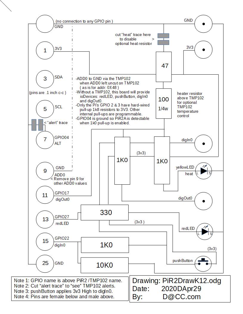
A few guidelines are useful when novices connect circuitry to the PiR2A or to the Raspberry Pi. It is possible to accidentally damage the Raspberry Pi. The "GPIO Wiring" guidelines diagram below provides some advice:
(To enlarge .....Click it.)
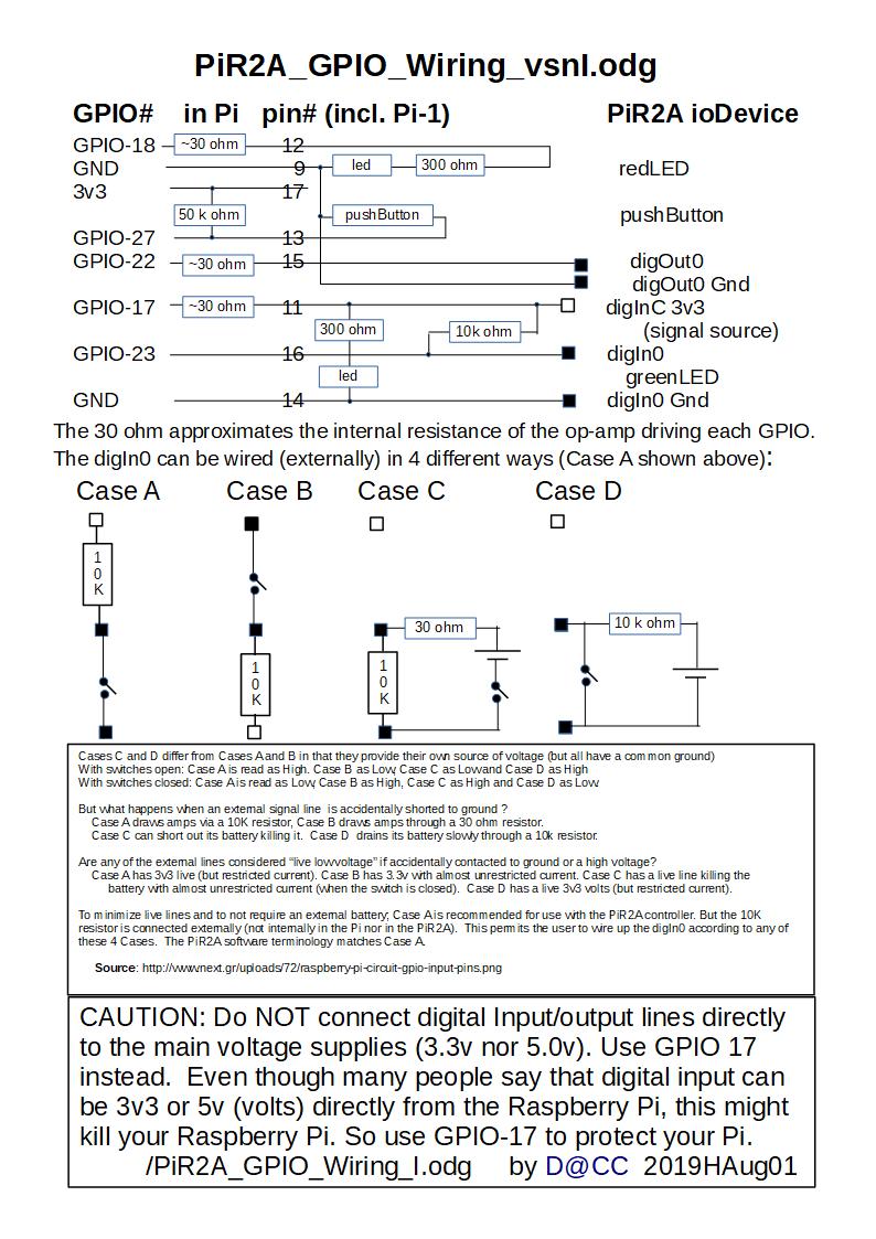
PiR2A GPIO Wiring
Typical PiR2 System
The diagram below illustrates a house where 2 PiR2 controllers are installed; one in the Basement and one in the Kitchen. Each controller operates individually to maintain control of its own area. The owner of the house can sign into the MehInCharge.com website where he/she can monitor and/or control each PiR2 controller. To date, each PiR2 controller operates independantly. The owner of the house can control each PiR2 controller using its Control Panel. Or the owner can use a local laptop (attached to the same router) to control either PiR2 controller. By signing into the MIC website, the owner can monitor and control either PiR2 controller from anywhere in the world via the internet using a tablet (iPad, computer, etc) or cell phone. [Ed. Note: As of 2020 E May, the PiR2 controller has not been sufficiently developed to establish communication with the website without an operator being at the keyboard of the Raspberry Pi.]
(To enlarge .....Click it.)
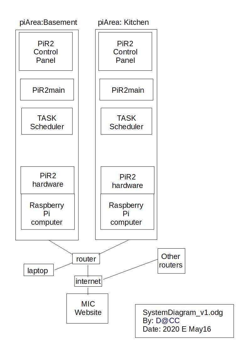
SystemDiagram_v1.jpg
PiR2 Software
At this time, the PiR2 system is comprised of the PiR2 hardware and the following 4 distinct software modules:
- PiR2A main software that controls the log and the PiR2 hardware components. It is comprised of:
-PiR2main.py which is the main program
-PiR2A which contains all of the routines called by PiR2main
-PiR2Data which assigns values to the main data file and list of files with their paths
- TASK software that schedules the PiR2 tasks that run on the Raspberry Pi
- PiR2 Control Panel that provides the interface to the Operator
- MehInCharge.com (MIC) web site
The first 3 software modules listed above are all written in python version 3. They run together on each Raspberry Pi. The PiR2A software was all written by the author with the exception of some python subroutines that are in the public domain. The Control Panel is the main GUI interface connecting the PiR2 hardware and software with the operator. The main link between the Control Panel and the PiR2 software is the r_v array. The r_v array holds the most recent values of each parameter of each ioDevice in the PiR2 system. The PiR2 software logs every reading and every control action. The log is a timestamped record of activity in the area around the PiR2 controller. From time-to-time this log is synchronized with the MIC website. This log is the main link between the PiR2 software and the MIC website. The simple TASK system was written by the author to invisibly schedule the various tasks that comprise the PiR2 system. The task-schedule file (the task queue) is the main link between the TASK subsystem and the PiR2 subsystem.
The PiR2 software is able to communicate with the operator in all the following ways:
- TV monitor(s) both audio and video
This permits the following types of interactions:
-displaying an image on a TV monitor
-sounding an alarm via the TV audio
-playing a tutorial video
-displaying the ongoing log
-permitting concurrent web surfing by the operator
-causing the PiR2 to speak messages (such as reading logs using a "robot" voice)
- Turning the redLED on/off
- Noticing when the pushButton is pressed by the operator
- Announcing an alarm via the TV audio
- Providing web access via the internet
�- Using an email facility (to send emails to the operator and/or others.)
- Accessing a web site (Source 01) where log records can be synchronized, filed for the long-term and displayed in a data table or graph format.
The MehInCharge.com website is described below. Its name implies that the PiR2 CONTROLLER gives its owner the ability to "be in charge" (i.e. control) the environment of the area near the PiR2. A future ioDevice that is planned for the PiR2 is a USB connector that can be used to recharge a device such as a cell phone or tablet. The PiR2 will be able to turn on/off the USB connector and also measure how fast the device is being charged. In this manner, the PiR2 CONTROLLER monitors and controls the charging of the device. This play on words resulted in the name of the website.
MehInCharge.com (MIC) website
This MIC website was written to communicate with a large number of PiR2 controllers. Any owner of PiR2s may have a number of houses or buildings. Each house (or building) can have 1 or more PiR2 controllers which are used to control the environment in its immediate surrounding area. (It is not coincidental that the formula for the area of a circle is PiR² ). Both the PiR2A and the Raspberry Pi computer are very inexpensive. More information about the PiR2A and the MIC can be found in the rightmost top corner of the MIC site below the menu item labelled "_ABOUT_ by clicking on the ".PiR2." and "Help" buttons. Without going to the MIC website, the article at Source 01 provides much more information about the PiR2 and the MIC website. The author has not yet begun to manufacture PiR2 controllers and offer them for sale.
Conclusion
As can be seen from the photo of the prototype at the beginning of this article, the PiR2A controller is a very simple device (Source 03) requiring no transistors, just seven small resistors, 2 LEDs and a push-button. The author has written many articles about his development of this system. Many of these articles can be found below by clicking on "Return to . . ePC Articles by Old King Cole". (Look for the articles with the prefix "Pi:"). The pdf document (in Source 02 below) provides many details about the electronics in the PiR2A CONTROLLER and how to use the various software modules in the PiR2 system.
The electronic footprint of the PiR2 controller is very small because of its use of powerful I2C devices. (See Source 06 for an I2C Tutorial). Many such devices are available because the I2C bus is being incorporated more and more into today's modern automobiles. The I2C devices simplify DAC (data acquisition and control) while reducing the wiring in an automobile. Their success keeps the cost of these I2C devices very low. It is very fortunate that Eben Upton, the designer of the Raspberry Pi, has advocated the use of I2C devices ever since his earliest models of Raspberry Pi computers back in 2012. His most recent model of the Raspberry Pi is the model 4B with 2GB of ram (membory) and 2 TV monitor (HDMI) connectors. It's price is just US$35 in 2020 B Feb 29. (To avoid power supply issues, purchase the official Raspberry Pi 3 amp power supply when you purchase the Pi model 4B.) In model 4B, Upton has increased the number of I2C busses on the Raspberry Pi to at least 6. This greatly increases the number of IO Devices that the Raspberry Pi can handle (See Source 04 ).
The Raspberry Pi computer with its I2C bus is an extremely powerful little gadget. For this reason, the PiR2A board, the Raspberry Pi and the PiR2 software coupled with the MIC website are very interesting. (Beginners might be interested in the "Thing" in Source 07) The PiR2 provides novices with a low-cost introduction to the field of process control. This allows powerful local area monitoring and control (with no monthly charges). The next addition to the PiR2 controller will be the Raspberry Pi surveillance camera . . . Watch for it.
INA3221 triple ADC Schematic (US$9.95)
(To enlarge .....Click it.)
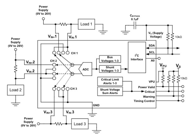
INA3221_Schematic.jpg
The circuit above is an inexpensive triple voltage comparator (A to D) from SwitchDoc.com. See Source 10 below.
INA219 single ADC (US$9.95)
(To enlarge .....Click it.)
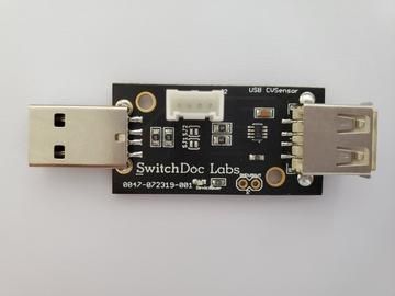
INA219_1_360x.jpg
The above device (A to D) reads USB current and voltage. It is from SwitchDoc.com. See Sources 09 and 11 below.
Need to measure current and voltage through a USB cord programmatically? Gather lots of
data dynamically? Then you need a USB CVSensor.
The USB CVSensor is an USB to USB current and voltage measuring device. It uses an INA219
to accurately (and dynamically) measure currents and voltages through a USB plug.
Measure:
Startup Currents and Voltages
Track Dynamic power consumption in systems
Gather data using Arduino or Raspberry Pi base systems.
External Sources: Books & Publications
-none-
Web Sources
Web Source S139:01: Pi: MIC - Meh In Charge .com (128.html)  Date: 2019 H Aug 16 by David AT ColeCanada.com
Web Source S139:02: PIR2 CONTROLLER FUNCTIONALITY V8  Date: 2020 D Apr 27 by David AT ColeCanada.com
Web Source S139:03: PIR2A Schematic Drawing v K12  Date: 2020 D Apr 29 by David AT ColeCanada.com
Web Source S139:04: Pi: Electronics for the Raspberry Pi Computer (130.html) Date: 2020 D Apr 21 by David AT ColeCanada.com
Web Source S139:05: IS: Pi Zero - US $ 5 (107.html) Date: 2015 L Dec 30 by David AT ColeCanada.com
Web Source S139:06: Raspberry Pi SPI and I2C Tutorial Date: 2018 H Aug 17 by J. Byron and Shawn Hymel of sparkfun
Web Source S139:07: US$17.95 ESP8266 "Thing" Hookup Guide Date: 2015 May 21 by JIMBLOM of sparkfun
Web Source S139:08: AtoD 12 bit I2C 4 channel Converter US$9.95 Date: 2020 E May 17 by Adafruit
Web Source S139:09: CVSensor - USB to USB Current / Voltage Sensor - I2C INA219 US$9.95 Date: 2020 E May 17 by Switchdoc store
Web Source S139:10: 3 Channel Current / Voltage - I2C INA3221 US$9.95 Date: 2020 E May 17 by Switchdoc store
Web Source S139:11: pypi.org for INA219 US$9.95 Date: 2020 E May 17 by Switchdoc store
Web Source S139:12: PiR2 Data Log System Definition V11 Date: 2019 E May 17 by David AT ColeCanada.com
Web Source S139:13: PiR2 Data Log System Definition V15 Date: 2022 B Feb 28 by David AT ColeCanada.com
Created 2020 E May 04
Updated 2023 H Aug 06
(c) ICH180R2
/139.html
 Date: 2020 D Apr 29 by David AT ColeCanada.com