179 Pi: Pix Explorer RPC (179.html)
Keywords
"digital communication" Explore and Adopt "Explore and Adopt" ExploreAndAdopt ExploreAndAdopt.py Asynchronous 9600 8N1
master slave bit byte character bps baud Tiny2040 RP2040 RTOS NullCQ RPC client server PuTTY Wio Terminal
"serial USB" ASCII "Extended USASCII" RS232 "USB Monitor" "USB Monitor Circuit" ICH180RR ADC A0 A1
BitScope DSO UART Bluetooth "RPi 5" bookworm error "GPIO 14 and GPIO 15 of J8" UART0 UART1 PL011 "mini UART"
"symbolic links" "System Console" "BitScope Clusters" "slave nodes"
KeywordsEnd
(To enlarge .....Click it)

IX or DC (IX by DC) or "|><"
This software is a part of the IX family of software.
Introduction
WARNING: None of the programs described below have yet been coded (except minicom and PuTTY).
The type of technology is called RPC (Remote Procedure Calls). Articles 191 (Source 02) and 193 (Source 03) address this type of program in more detail. This program is my first attempt to design and develop a software tool that will explore the capabilities of an asynchronous serial communication facility. This software tool will be implemented on a Raspberry Pi computer connected to a Tiny2040 microprocessor board. A communications facility being explored will include the following:
-controlling (master or central or client) transmitter and (slave or server) receiver hardware
-slave transmitter and receiver hardware
-compatible communications software in the transmitter and in the receiver
-the transmission medium (usually a cable e.g. serial USB) connecting the master and slave hardware
-parameters being used to configure the software and hardware
-whether or not packetization is possible
-asynchronous serial communication will be explored, not synchronouse serial communmication
Communications Facility Example
A first example of an asynchronous communications facility is a Raspberry Pi computer running minicom connected to nothing via a USB cable. This is a transmitter sending data to a supposedly null receiver.
A second example is a Raspberry Pi computer running minicom connected to a Pi Pico microcomputer that is running the echoLines_pico.py program.
Note that 2 Raspberry Pi computers and 2 Pico microcomputers will be used when exploring the second facility described above, one pair being the facility being explored and the other pair being used to do the exploration. Other RPC systems such as eRPC and my future ixmRPC are intended to do a similar job. They are not descibed in this article.
Proposed Procedure
Most communication links must operate in a state using predefined parameters (e.g. 9600 bps 8N1 asynchronous ascii). Often an asynchronous serial link has the slave end (node) with well-defined (usually adjustable) parameters defined at start up time. At the master end (node), a human or smart software either already knows the exact parameters at the slave end, or has the capability to determine these parameters by trial and error. This article describes a
methodology that can be incorported into communications software to explore and adopt a workable set of communication parameters. This program will be called ExploreAndAdopt.py . In most cases, one or more voltage probes will be connected to a communications line via an appropriate capacitor. The voltage probed should be attenuated (lowered) sufficiently to ensure that the voltage does not exceed +3v3 nor be lower than 0 volts. The voltage on the communications line will be measured using an ADC port on a Raspberry Pico or on a Wio Terminal.
Exploratory Programs
The following recommended programs (or protocols) pertain to an asynchronous communications channel (link):
SendRecv         - Program (future) to send and receive messages using an (ultra simple) link
NullCQ           - Program (future) or function that can be used to establish Pix/pktix communications between 2 nodes.
                      (The function returns the bit rate, byte format, packet status and list of nodes on the link.)
                         e.g. "9600-8N1,P ,S"  or "155200-8N1,PA,fa13,0001"
EchoLines        - Program (future) that simply echoes single messages back to the other node
                         (Each message must be terminated by a LF.)
DetectParameters - Program (future) to detect (on an ongoing basis) the characteristics of a specified communications link
ListenAndRecord1 - Program (future) to listen to a unidirectional communication link and report what it "hears"
ListenAndRecord2 - Program (future) to listen to a bidirectional link and report what it "hears" in each direction
ExploreAndAdopt  - Program (future) to explore a link and adopt a workable communications protocol
SelectAndAdopt   - Program (future) to define the methodology of this end of a link and adopt it
Pix              - Program (future) to communicate and transmit/receive files between nodes
                       (The first character of each non-packet message is a space.)
Pix@             - Program (future) to communicate and transmit/receive files to a specific node (
                       by specifiying its address)
                       (The first part of each message contains its address e.g. space,node-address,space (without commas)
pktix            - Protocol (future) function using packets of pre-defined lengths.
                         (Each packetized message is enclosed in "[" & "]")
minicom          - Program (existing) that emulates a VT100. It can also send/receive files.
                         (Install using Raspberry Add Software)
                         (Then start it in Terminal mode on a Raspberry Pi by typing:
                             "minicom --device /dev/ttyACM0 --color=on"
PuTTY		 - Program (existing) that is similar to minicom, but is more recent
Each of the above programs (except minicom) are or will be written in Python for the pico. The exact program name will have a suffix of "_pico" and an extension of ".py".
All of the above master programs (running at a node), except minicom, send an ascii NULL (0x00) or the character "0" (0x30), or these characters alternating once every 10 seconds at 9600 bps to show evidence of life on an otherwise quiet link. A single slave will reply with an NULL character (0x06) at 9600 bps if it has nothing to send. Other quiet link sequences have not yet been defined.
Using minicom on a Raspberry Pi
To use minicom on any Raspberry Pi, simply do the following:
1. Use the Raspberry Pi menu to add the "minicom" software application
2. Start up Terminal to accept Linux command lines
3. Enter:
      >>$ minicom --device /dev/ttyACM0 --color=on
4. Enter
      >>$ Ctrl-A Z
5. Select the minicom communications parameters
6. Type ? to Exit setup
7. Type any message (followed by LF) and it will be sent
8. Any returned messages will be displayed.
7 bit US ASCII Table and the serial character structure
The most common serial characters are defined in the 7 bit US ASCII table shown in Web Source 01 below. When transmitting, a quiet link sends continuous 1 bits. When a serial character is to be sent, the first bit (the start bit) is a "0" bit followed by bit 1, bit 2 through bit 7. These data bits are followed by a parity bit, which can be defined in four ways: Even, Odd, Mark, Space. This series of bits is followed by 1 or 2 stop bits which are 1 bits. Such a character structure might be called 7-E-2 which means 7 data bits, an Even partity bit and 2 stop bits. Another character structure is 8-N-1 which means 8 data bits, No parity bit and 1 stop bit. The latter is often used to transmit 8-bit Extended USASCII characters. When an RS232 line is used, a high (1) bit is a negative voltage. When TTL, CMOS or HC logic is used, a high (1) is a positive voltage; a 1 is often approximately +3v3. In Raspberry Pi and Pico processoring, it is presumed that USB signals resemble a HC signal.
visual representation of a serial "0" (0x30) character in 7-O-2 format
                             1    1    0    0    0    0    0    1    1    0    1    0    0    1    1

                          Idle  Idle Start  b1   b2   b3   b4   b5   b6   b7 Parity Stop Stop Idle Idle
                             t01  t102 t03  t04  t05  t06  t07  t08  t09  t10  t11  t12  t13  t14  t15

A serial character appears in the above sequence on an oscilloscope (that displays time going left to right).

The actual digital character sequence viewed on oscilloscope (or logic analyszer) would be as shown below:


                        _ _ ________                            _________       ____           _________ _ _
                                    |                          |         |     |    |         |
                                    |                          |         |     |    |         |
                                    |__________________________|         |_____|    |_________|

                         Idle Idle Start Data  Data  Data  Data Data Data Data Parity Stop Stop Idle Idle

           time:             earlier    ------>      ----->      ----->     ----->       later
Note that the character is displayed "backwards" (left to right) on the oscilloscope as 0x0C (excluding the parity bit) but is stored in
a computer as 0x30.
When deciphering the arrival of a serial character, the electronic circuit must detect the (first) descending edge
of the start bit. Then after a time interval of 1/2 a bit, it samples (at midpoint) the state of the incoming signal to
determine if it is high or low. Then after subsequent intervals of 1 bit it samples the midpoint of each subsequent bit.
This continues until the last stop bit of each character. After sampling the midpoint of the (last) stop bit, it begins
to search for the arrival of the leading (descending) edge of the start bit of the next character. In an asynchronous
serial message the next character can begin at any time, even seconds after the previous character. To correctly sample
each bit of an incoming character, the transmitting bit rate (bps) should be known in advance.
An 8 bit ascii character of special interest is the 8-bit USASCII character NBSP (0xAA). When transmitted in 8N1 format, it is sent
as 1010101010 which is a bit stream of five sets of alternating 0's and 1's. The character that it represents is a
Non-Breaking_Space (NBSP). When analyzed, this character readily defines the bit rate of the transmitter by providing 9 equally spaced edges. Another interesting
character is the capital D with a dash (0x0D). This character is 00001101, which a bit stream with edges at different intervals. Another interesting character is the lower case "a" with two dots above (0xE3). This character is 11100011 which is low for 1 bit time, then high for 2 bit times, then low for 3 bit times, then high for 4 bit times continuing high after that. This character provides 4 edges at different known time intervals.
Perhaps, in N81 format the most useful character, for determining the incoming bit rate is the NULL (0x00) character, sometimes referred to as Null. Including the start and stop bits,
this character is 0000000001. This character provides a leading edge (of the start bit) followed by 9 bit-time-intervals followed by the leading edge of the stop bit. A quiet electronic circuit can easily continuously measure these time intervals. Within a random message stream that contains one or more NULL characters, the longest number of bits measured is 9 times the bps rate. Simply dividing this longest number by 9 gives the bit interval which is the inverse of the bit rate. On a quiet link, if a NULL character is sent once every 9 seconds, the receiver (slave node) can easily know the exact bps rate of the transmitter. If the slave waits 9 character times and returns a NULL character, the transmitter (master node) will know that the receiver's bit rate is synchronized with the transmitter. Fortunately, the meaning of a single NULL character is a message (or character) that can be ignored.
Node Identification
After the bit rate (and byte format) have been agreed upon (e.g. 9600-8N1) , the master and slave nodes can begin to exchange information. A means of identification (name or address) is often used, although it is not necessary for communication. If the transmitter follows the Null character immediately by the 2 letters "CQ" (borrowed from Amateur radio messaging where it means "seek you"), the slave node can reply with its identification. A nameless slave node should reply Null followed by an "S" for slave. If the reply is an "M" then the slave is requesting to become "Master". If this is acceptable, then the reply from the original transmitter should be NULL followed by an "S". In this manner, the two nodes can agree on their "Master-Slave" relationship. If the node replies with any non-empty character string other than "S" or "M", then this is understood to be the address of this Slave node. If more than one Slave nodes sends a valid (non-erroneous) message, then the Master will resend the NULL-CQ sequence. If these replies contain an error, each of the slave nodes should identify itself after a 4 to 400 character time delay, chosen at random by each slave. The Master node should keep a list of all the Slave nodes currently identified on this communications link. A future program that can be used to establish this relationship is NullCQ_pico.py
After this exchange of identifications, the Master should always preface each message with an address prefix which is "[< address >]" followed by enough "]" to make a full packet, if packets are being used. Note that any "]" or "/" must be escaped in a node address. Each occurence is escaped by preceding it by a "/". If packets are not being used, then such escaping must be done in every message.
If only one slave node exists, the Pix system requires that:
1. Master and Slave nodes will begin using the 9600-N81 byte format
2. the Master node does not need to prefix each message with an address prefix (but this is recommended).
3. packets are not necessary, but they can be used
4. characters can be sent one at a time at irregular time intervals, as when typing
5. each message sent by the master node must receive a reply from the slave node (ACK being the shortest reply).
6. no error checking is required, but is welcome. Any error triggers an immediate NAQ.
The NAQ is sent immediately and again as soon as the transmitted stream is quiet for 2 character times.
7. each "]" and "/" should be escaped by a prefix of "/" when packets are NOT being used.
However, the Pix system is forgiving if the "escaping" is omitted.
8. If a digital scope is being used, it should keep track of (count) the errors in the transmissions and
should display these statistics in real time. A Wio Terminal is ideal for use as a
In modern (c2023) links, there is very little noise therefore no error checking is done, except when
packetized methodology is being used.
end of mandatory protocols.
Pix Serial USB Monitor Cable by ICH180RR
An electronics buff will have little difficulty monitoring a bi-directional serial USB line. The easiest way to do this is to have a device called a USB Monitor Cable as shown below:
USB Client Connector             USB Monitor Cable   	        USB Server Connector
     (Master)                   					(Slave)
  eg Raspberry Pi						  eg. Raspberry Pico
--------------------    -----------------------------------     ---------------------
     female USB						    	     male USB
	pin								pin
3-5v	 1  ----x------------------------------------------------------  1
		|
send	 2  ----------------------------x------------------------------  3
		|			|
receive	 3  ------------------------------------x----------------------  2
		|			|	|
ground	 4  ----------x------------------------------------------x-----  4
		|     |			|	|		 |
		|     x--1K0--x---9K0---x	x---9K0--x--1K0--x
		|             |		|	|	 |	 |
		|     	      |	  	|	|        |	 |
	        x-T2          |	  T0----x       x-T1     |    T3-x
		|      	      |	  	 	         |       |
	       3-5V          A0   	      	         A1     Gnd
         (middle-right   (left-most             (middle-left  (right-most
               pin)         pin)                        pin)    pin)
               . . . . . . . . . . . . . . . . . . . . . . . . . . .
		      Male Grove Connector (on left back of)
				 The Wio Terminal
The above cable (and circuit) will measure signals that have been attenuated by a factor
of 10. The serial USB signals going between the Raspberry Pi and the Raspberry Pico remain
unattenuated. The signals that are measured are lower voltage (attenuated) signals. They
have been dropped by a factor of 10 to under .5 volts. (These lower voltage signals are
very safe when they are "read" by the 2 analogue inputs on the Wio Terminal.)
The 3 connectors make the
"Pix Serial USB Monitor Cable" very easy to use because no soldering is required. A simple
software program (written in Python) can monitor and provide a digital report of the serial
USB signals going between the Raspberry Pi and the Raspberry Pico (or any other Slave USB device).
The little circuit board in the Monitor cable has four terminal posts: T0, T1, T2 and T3 to
permit other Voltage measurements but only use these terminals if both USB cable connectors
are NOT connected to anything. The signals on T0 and T1 are also attenuated by 10.
The Grove connector on the US$40.00 Wio Terminal (Source 04) permits the Wio Terminal to monitor
the two Analogue Input (ADC) sensors on the Wio Terminal Grove Connector. The Wio Terminal is
necessary because the Raspberry Pi does not have any Analogue ADC sensors. The program can
report its results on a tiny LCD screen what data is being sent between the Master and the
Slave. The Wio Terminal can save a
record (to a uSD card) of all the data being Transported (in both directions along this serial
USB channel. This monitoring activity is completely non-intrusive and does not affect the
communications between the Master and the Slave. A well-designed program will readily detect
the speed (bits/sec) of the ASCII characters that are transmitted and received. Usually the
speed is either 155,200 bits/sec or 9,600 bits/sec. The program should initially presume
that the speed is 155,200 bits/sec. This program is intended to be used with minicom or
PuTTY or the standard Raspberry Pi to Pico interface.
This program only displays USASCII characters. Other characters may be garbled.
Note that, if it is not supplied with power directly, the Wio Terminal will take a little power
from the Raspberry Pi via the USB cable.
Tutorial on Aynchronous Data by Brad Solomon
Source 05 by Brad Solomon provides a technical description and examples of Python code. He imports and uses "asyncio". Beware: "asyncio" is a very complex MicroPython library of interrupt-driven routines to read/write serial async data.
Raspberry Pi Serial Ports
The webmaster recently (2023KNov19) discovered an article (Source 12) about Raspberry Pi Serial Ports. What caught my eye was:
bookworm has introduced at least one bug in the handling of serial ports on Raspberry Pi.
This is of special interest because bookworm OS is the only OS that works on the recently released Raspberry Pi 5. Furthermore, the RPi 5 has a new RP1 chip that handles the GPIO pins. Also, the RPi 5 has a new Serial port ( UART ttyAMA3) that is mentioned below and in Article 206. The 3 pin connector for this new serial port (and UART) is physically located between the 2 HDMI micro connectors on the RPi 5 (see image below).
(To enlarge .....Click it)
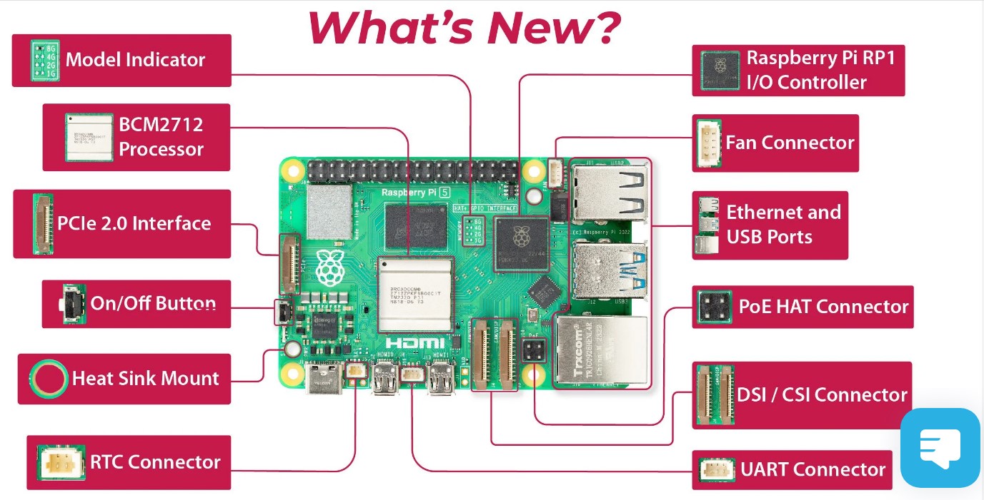
UART Connector on RPi 5 Interface Diagram
This additional RPi 5 UART has a separate connector and is NOT on the GPIO pins. Cytron (in Source 13 and Source 14) provides some information about using this UART connector with the RPi Debug Probe and the RP2040. In Source 13, in notes about the RPi 5, Cytron states:
Dedicated UART debug port, independent from 40-pin GPIO. Always Enabled
These simultaneous changes and the bug mentioned above, provide fertile ground for hardware and software errors. BitScope DSO is an oscilloscope often used with digital computers. Of interest to the webmaster is the special attention recently paid to Raspberry Pi Serial Ports by the people who manufacture and support the BitScope DSO, those who wrote the article in Source 12. Interested readers (especially users of Bluetooth) might find the article in Source 12 of special value.
The PL011 (on the RPi 4 only) has UART2, UART3, UART4 and UART5 assigned to specific GPIO pins. PL011 on the RPi 5 is unknown (as of 2023KNov19). Linux devices /dev/ttyAMA0, /dev/ttyS0, /dev/serial0 and /dev/serial1 are mentioned in Source 12. If you are dealing with "BitScope Clusters", when changing rasp-config or /boot/cmdline.txt, they (at BitScope DSO) suggest:
Be sure not to accidentially change anything else in /boot/cmdline.txt .
If you are encountering serial UART issues on a Raspberry Pi, the article at Source 12 might be of special, even critical, importance. The novice UART user should study the differences between USB serial communictions and non-USB UART serial communications. To repeat the words of someone at BitScope DSO: caveat emptor (although those words originally pertained to exceeding permitted signal voltage levels). The webmaster intends to study these UART issues in more detail at some future time. The webmaster would be interested in communicating with anyone who has recent experience or knowledge about these UART issues on Raspberry computers and/or microcomputers. Hopefully future documentation about the new RP1 chip will answer some of these questions.
The Raspberry Pi 5 was announced in September of 2023. It provides an external UART connector (previously mentioned) as distinguished from a USB connector. The RPi 5 male UART connector is designed to communicate with a Raspberry Pico using the RPi Debug Probe, but it surely will be usable for any type of asynchronous serial communications. For more information about the RPi 5 UART, see Article 206. The RPi 5 UART connector has only 3 pins (Source 11 and the image below). It appears to use HC logic levels of 1.8v and +3.3v +-10%). It differs from the ancient 9 pin RS232 connector that has other signals such as Carrier Detect, Request To Send, Clear To Send etc. The RS232 also uses different logic levels. Documentation of the RPi 5 software support for the new UART is sorely lacking. (Please notify the webmaster if you know of any such documentation.)
(To enlarge .....Click it)
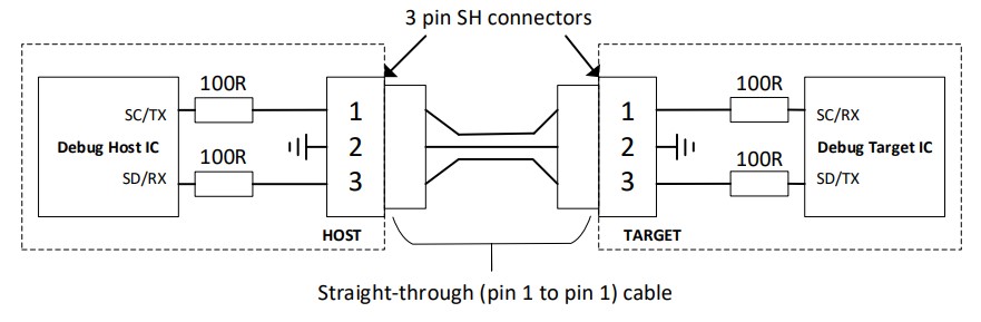
RPi 3-pin UART Connector
from Source 11
Other Notes
Source 06 by MicroPython describes using an RP2040 "state machine" for bit-banging.
Source 07 by MicroPython refers to the complete set of MicroPython documentation. (www is a current version).
Source 08 by BBOYHO of Sparkfun points to one of a series of articles about async signals.
Source 09 by peterhinch describes how to wait until the ADC is within range (in MicroPython). This is very useful when reading the next character by "bitbanging".
Source 10 by D@CC which describes a Main Menu program for the Wio Terminal.
Sources
Video Sources
Video Source V179:01:
First Look at the Tiny2040 (3:14 min)  by Learn Embedded Systems c2021DApr
Video Source V179:02:
Free RTOS on the RP2040 (13:44 min) by Learn Embedded Systems c2021DApr
Web Sources
Web Source S179:01:
7 bit USASCII table 
Web Source S179:02: www
A&C: PiR2W Controller (191.html)
by D@CC as of 2023DApr24
Web Source S179:03: www
A&C: ixmRPC (eRPC lite) Remote Procedure Calls (193.html)
by D@CC as of 2023DApr24
Web Source S179:04: www
Pi: Wio Terminal for Raspberry Pi (186.html)
by D@CC as of 2023DApr24
Web Source S179:05: www
Async IO in Python: A Complete Walkthrough
by Brad Solomon as of c2019AJan16
Web Source S179:06: www
Programmable IO : BitBanging / StateMachine / rp2 / MicroPython
for RP2040 as of 2023DApr27
Web Source S179:07: www  micropython-docs.pdf
by MicroPython as of 2023DApr27
micropython-docs.pdf
by MicroPython as of 2023DApr27
Web Source S179:08: www
serial asynch vs parallel etc etc
by BBOYHO of Sparkfun c 2017HAug24
Web Source S179:09: www ADC monitoring (.aadc to wait till "within range") by peterhinch @ github prior to 2023
Web Source S179:10: www
Wio: wioMainMenu (190.html)
by D@CCon 2023DApr29
Web Source S179:11: www
RPi 3-pin Debug Connector Specification
by Raspberry Pi before 2023JOct09
Web Source S179:12: www
Raspberry Pi Serial Ports
by BitScope DSO on 2023JOct27
Web Source S179:13:www
The Raspberry Pi 5 SBC
by Cytron on 2023 I Sep 28
Web Source S179:14:www
The Raspberry Pi Debug Probe for the RP2040
by Cytron on 2023 I Sep 28
WebMaster: Ye Old King Cole
There is a way to "google" any of the part-numbers, words or phrases in all my articles. This "google-like" search limits itself ONLY to my articles. Just go to the top of "Articles by Old King Cole" and look for the "search" input box named "freefind".
Date Written : 2022 F Jun 05
Last Updated: 2023 K Nov 19
Font: Courier New 10
/179.html