191 A&C: PiR2W Controller (191.html)
My previous article (190) introduced the wioMainMenu program for the WioTerminal (Source 11). Another significant application of the WioTerminal is for Acquisition and Control (ie Sense and Control) such as my PiR2 Temperature Logger. The PiR2 (Source 12) application can make significant use of the WioTerminal. In fact, it was the PiR2's need for many of the features of
the WioTerminal that got my attention. This article describes in detail, my new PiR2 model: the PiR2W. It might not even need a Raspberry Pi computer nor a PiR2P board, just a remote temperature sensor with a Grove connector and, of course, the Wio Terminal. If the pir2 software cannot be fully ported to the WioTerminal, the PiR2P will be necessary (instead of the PiR2PAda) in the PiR2W.
Keywords
"191 A&C: PiR2W Controller (191.html)" A&C PiR2P
"Acquisition and Control" "Acquisition & Control" Acquisition API Benchmark CfromF Chassis-Battery "Chassis - Battery" c-wrapped CMOSens codec Control CRS .crs Cytron D@CC Dhrystone "Enter key" eRPC "eRPC function names" Geppetto github Grove Hinge ICH180RR IDL .idl "improvised function" inCharWto inputWto Invert ixmRPC LCD LoRa Maker "Maker pHAT" MehInCharge.com MehInCharge "Meh In Charge" MicroPython Mouser multi-color-monitor pHAT PiR2 PiR2A PiR2D PiR2P PiR2PAda PiR2W PiR2WL PiR2_Hinge Port py Python Port Raspberry Reading RGB RPi Sense Sensirion "shim code" SHT31 SHT31-D SHT31 SHT31-D SHT31-DIS-B starboard "temperature sensor" tinkercad tinkergen tool "traffic light" uJoyStick Unity uSD WioTerminal Z-base "Uber Home Automation" OpenHAB Arduino
KeywordsEnd
(To enlarge .....Click it)

IX or DC (IX by DC) or "|><"
This prepIX.py software is a part of the IX family of software.
PiR2W Controller
(To enlarge .....Click it)
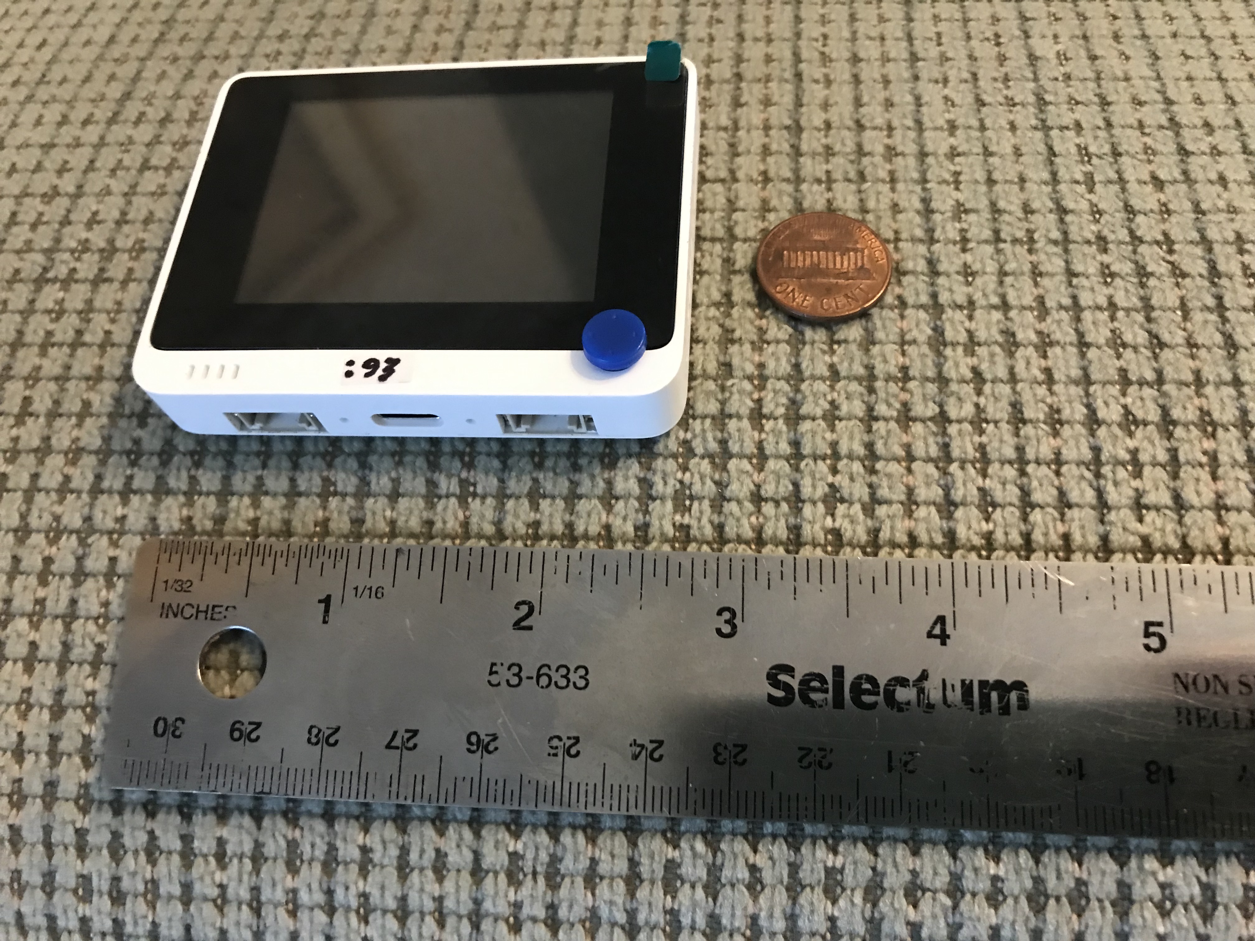
The tiny Wio Terminal
|
(To enlarge .....Click it)
PiR2W mounted on a RPi
|
The PiR2W makes major use of the peripheral devices already in the Wio Terminal (Source 11). This means less (or perhaps no) soldering which is always desirable. The three switches on the edge of the WioTerminal can be used as-is. However three LEDs ( Red, Yellow and Green ) are desirable but optional. They can easily be soldered onto the Adafruit 4132 RPi "Hat" or to the PiR2P board. This article describes how the WioTerminal, the PiR2P Proto Board (or the PiR2PAda Adafruit 4132) with the three additional LEDs) and a Raspberry Pi board can easily become the PiR2W controller and/or fridge monitor. The PiR2P can accept an external 5v0 source. A jumper exists to permit this source to power the RPi and/or the WioTerminal as well. The TMP36 on-board the PiR2P can be used to measure the ambient (room) temperature while the remote temperature sensor can be sensing the temperature inside a fridge or freezer. An electronic "closed loop" control system does not exist for the fridge or freezer. In case of problems with a fridge or freezer, all that can be done by the WioTerminal is to sound an alarm and send an email to someone who hopefully will come and remedy the situation. A future version of the PiR2W is planned with a usable light detector. This PiR2WL will reside inside the fridge or freezer and will detect the door being left ajar. (When the door is ajar, the internal light will be ON, which can be sensed by the Wio Terminal.) A buzzer will be sounded, to perhaps alert the (hopefully still nearby) person who left the door open.
Table of Contents
A&C: PiR2W Controller (191.html)
Table of Contents
Introduction
Grove - Temp & Humidity Sensor ( SHT31 )
The Grove Connector
The Wio Terminal's GPIO Interface and It's Internal Devices
My Versions (models) of PiR2D-like Devices (latest PiR2W [fut] )
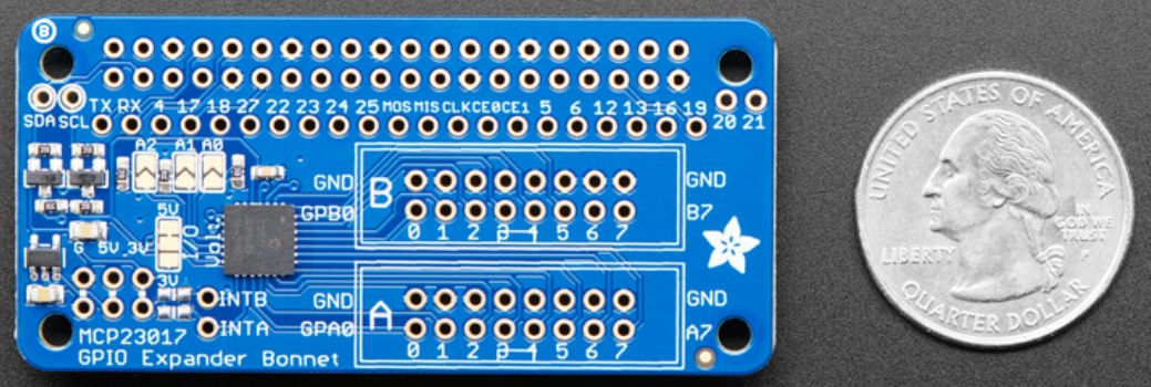
The Adafruit 4132 board: GPIO Expander Bonnet
Orientation of the 3 LEDs for the PiR2W
A Stand (Base) For the PiR2W
The Hinge Pieces
Schematic of the PiR2P
Wiring Diagram of the PiR2P
Boards Making Up the PiR2W
A More Detailed Description of the PiR2W Boards
Power and On/Off Switches
The Amazing and Simple Design of the WioTerminal!
"Wio Terminal" Review by Hackster.io
A Remote Outdoor Air Quality Monitor Display
Using ide.tinkergen.com on the "Wio Terminal"
eRPC: Getting Started
The New Wio Terminal eRPC (embedded Remote Procedure Call) Firmware
UPDATE: WiFi and BlueTooth Are Now Operational
Other Related Thoughts
Conclusion
End of Article
Sources
Introduction
The WioTerminal seems to have been designed to be used as a small Acquisition & Control device. It has all of the capabilities needed. The only electronic devices that optionally need to be added are three LEDs. By soldering these 3 LEDs to the PiR2P (or an inexpensive Adafruit 4132 board) the PiR2W is complete. Because MicroPython software for the RPi and the WioTerminal is somewhat compatible, perhaps the WioTerminal can effect the control without need for the more expensive Raspberry Pi-Based PiR2W. Only the SHT31 temperature/humidity sensor might be needed. A few other projects based on the Wio Terminal are listed in the Sources. Wow!
Grove - Temp & Humidity Sensor ( SHT31 )
(To enlarge .....Click it)
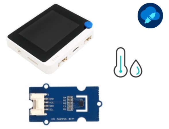
Grove WioTerminal and a SHT31
This I2C Grove device (shown above: a Seeed Studio SKU 101020212 US$ 9.90 ) uses I2C technology to measure temperature and humidity. It can be referenced at Source 09 below. It is based on the Sensirion SHT3x-DIS sensor. It can probably be used instead of the I2C TMP102 in the PiR2 system previously developed by the author. Minor coding changes would be necessary. The SHT31 is compatible with the WioTerminal. It uses CMOSens and I2C technology and is delivered with a Grove cable and connector. The SHT31 requires an unbuckled Grove cable. It has 2 user-selectable addresses. The main address of the SHT31 is I2C address 0x44. The SHT31 board design overview by Geppetto, is included as a pdf file at Source 09. A zipped copy of this same design is available at Source 04. Some of the information resides at github. Its github date is 2020CFeb03. A Library and example (c/c++) code can be found near the bottom of Source 04 (www).
The Grove Connector
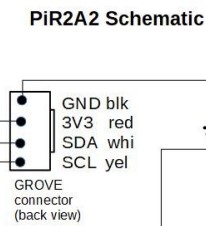
The Grove pin-out is GND, VCC, SDA, SCL . The back view of the Grove Connector shows that the GND pin is at the top. The image of the Grove connector shown below comes from Source 16 of this article (191). Source 16 includes a future "INA3221 Triple Load Current and Voltage Sensor (V07)". But Source 05 goes to "The INA3221 Breakout Board" which itself has a Source 06. That Source 06 is named "IT: INA3221 Current and Voltage Sensor". That Source 06 is actually titled "The INA3221 Breakout Board". The Schematic of the PiR2P appears under the heading of that same name. A portion (a snippet) of that image is shown below:
(To enlarge .....Click it)
Grove on the PiR2P
In this snippet (shown above) the GND pin is at the top when the connector is viewed from the back (where the wires come out) with a small "buckle" on the right. This snippet also shows the color of each wire. The black wire is GND, the red wire is Vcc, the white wire is SDA and the yellow wire is SCL.
Return now to the full image that appears later in this article, (where the snippet was clipped). We see the Grove Connector (where either the SHT31 or the TMP103 could be connected.) The main image, from Source 16, also shows a TMP36 temperature sensor. Any of the three temperature sensors (mentioned in this article) can be used with the PiR2W device.
(To enlarge .....Click it)
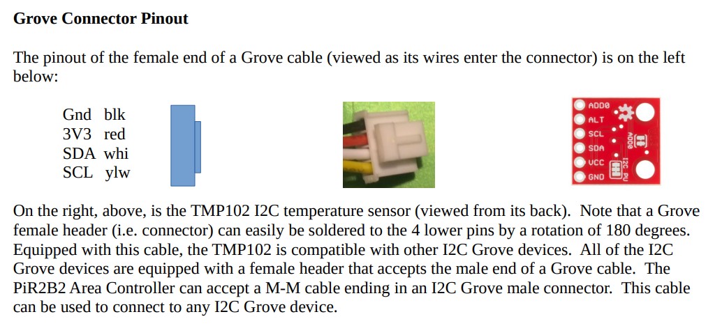
Grove Connector Pinout
More information about the Grove connector can be seen on page 4 of Source 01 from which the above image was taken. The Wio Terminal is equipped with this exact compatible Grove female connector.
The Wio Terminal's GPIO Interface and It's Internal Devices
(To enlarge .....Click it)
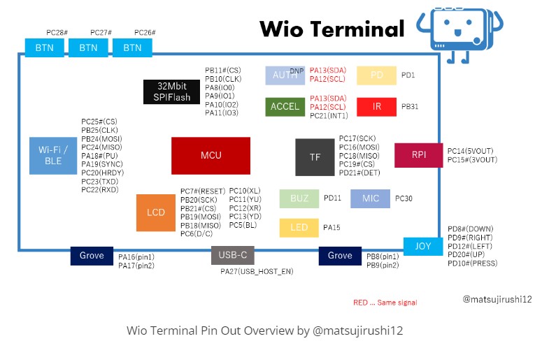
WioTerminal Pin-Outs (Features)
|
(To enlarge .....Click it)
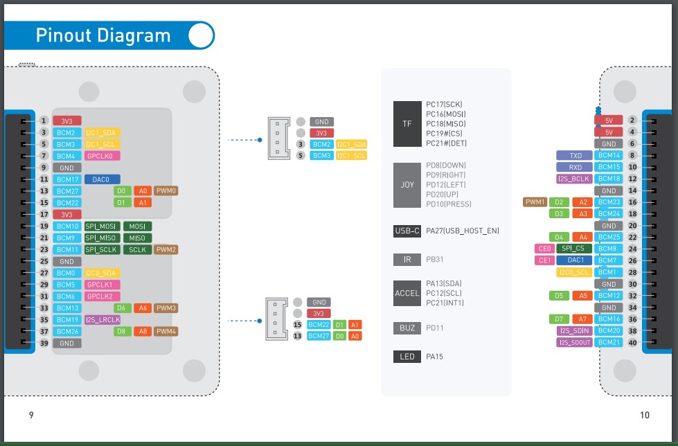
WioTerminal Pin-Outs Physical View
|
The Grove connector for external I2C devices is on the front left (bottom edge) of the WioTerminal. The Grove connector on the front right side (bottom edge) is for external ADC measurements (see "Best Pinouts" in Article 193). [ If I have them reversed, please let me know.] The button (of the 3 "top" buttons) that is closest to the left side (or corner) is PC28#. Beside it is PC27# and then PC26#. Beware that the light sensor and the IR LED on the back will both NOT be usable if anything is plugged into the back of the WioTerminal. Just recently, I learned that the IR transmitter and the light sensor (on the back of the Wio Terminal) can be used to communicate bidirectionally with another nearby Wio Terminal.
When the "Wio Terminal Chassis - Battery" is connected, it provides 6 more Grove connections and another USB-C port, although, the USB-C port on the Battery will probably be used to provide constant power to the "Wio Terminal Chassis - Battery" (and hence to the WioTerminal). If an RPi is used, it may require its own power supply. Although my initial tests indicate that it receives sufficient power via the USB connector on the WioT battery.
My Many PiR2D-like Devices and the PiR2W (fut)
Source 10 lists the evolution of my PiR2 devices resulting in the PiR2D device (and soon, to the PiR2W device). The author plans to design and build a new PiR2 device using the Wio Terminal. It will be called the PiR2W. This is a very attractive project because the Wio Terminal already houses many of the more complex components needed for the impressive PiR2W device. Most important are the 40 pin GPIO, the Grove connectors, the tiny LCD screen, the ADC capabilities, the battery (Wio Terminal Chassis - Battery) and the Buzzer. Only the 3 LEDs, the heating resistor (and possibly some light sensors) need to be added. All of these additions can easily be soldered onto a small "hat" board that would plug directly into the 40 pin GPIO pins on the WioTerminal. Software for the uSD card will need to be finalized. The three push-button switches on the edge of the WioTerminal can serve as input devices instead of the photocells (light sensors) and push-button on the earlier models of the PiR2. The log (and other information needing to be saved) will be written to the uSD card plugged into the WioTerminal.
On the PiR2W, the Red, Yellow and Green LEDs (Left to Right when viewed from the front of the Adafruit 4132) were (in Source 02) to be connected to GPIO pins 11, 08 and 07 respectively. There, the HEAT resistor was driven by pin GPIO09 (GPIO09 also served as Digital Out). The Yes and No buttons will be the "top" buttons numbered 1 and 3 respectively on the WioTerminal. Only 2 Grove connectors will be needed, one for the I2C temperature sensor and the other Grove connector for an optional ADC analog input point and/or the Digital Output. Any GPIO pins that "clash" will be handled by software. The PiR2D schematic at Source 02 shows that all other sensors and actuators can be provided by the WioTerminal itself. This future device, the PiR2W, based on the Wio Terminal, certainly is the best "fit" for an almost perfectly-ready-out-of-box PiR2 Device.
The Adafruit 4132 board, called a "GPIO Expander Bonnet", shown below, easily provides access to pins that drive the 4 digital outputs. The additional 16 pins on the Adafruit 4132 are driven by a MCP23017 multiplexer IC. Unfortunately the exact GPIO pins are not readily available on the Adafruit 4132 but pin re-assignments are not a big issue because they can be handled by software. This tiny, inexpensive, "hat" board (housing the 3 future LEDs) can easily plug into the back of the WioTerminal or to the back of the "Wio Terminal Chassis - Battery".
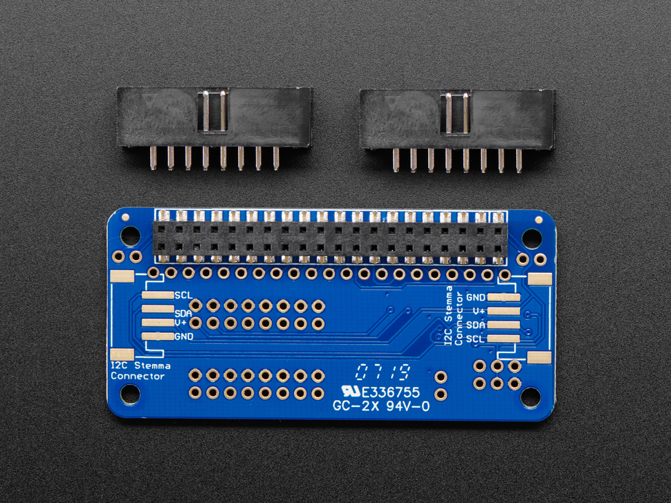
The Adafruit 4132 board: GPIO Expander Bonnet
The author planned to use the Adafruit 4132 (GPIO Expander Bonnet) as the board on which the PiR2W was to be built. He then discovered that it was not possible to attach both a male and a female 40 pin header to the Adafruit 4132. This meant that the Adafruit 4132 would only be usable when the RPi was NOT being used. So the model of PiR2 using the Adafruit has been renamed to be the PiR2PAda. The final PiR2P will be built upon the P1 Proto Board V1.1 from BC Robotics. It's schematic can be seen under the Heading "Schematic of the PiR2P" which is Source 16.
(To enlarge .....Click it)
Adafruit 4132 "Hat" for the Raspberry
|
(To enlarge .....Click it)
Adafruit 4132 "Hat" back view
|
The Adafruit 4132 "GPIO Expander Bonnet", shown above, is available from Mouser Electronics Canada for CAD$ 13.73 (DataSheet at Source 08). The small number of components on the future PiR2PAda will easily fit on the above small "hat" or "bonnet" that can be plugged into the GPIO pins on the WioTerminal. But the PiR2P is equipped with both male & female GPIO headers so that it can be sandwiched between the WioTerminal and the RPi. Hopefully, the software to drive the PiR2W can also be completely ported to the WioTerminal. Porting all the code to the WioTerminal (and the PiR2W) will permit the WioTerminal to be a stand-alone device with a uSD card to house the resulting data logs. The (schematic) drawing named PiR2WDrawA02.jpg in Source 16 will serve as the basis for a future schematic describing the circuitry "optionally needed" for the future PiR2P. [Corrections needed: 1. A1 for A0 2. Reposition R6 label 3. For Article 191 ]
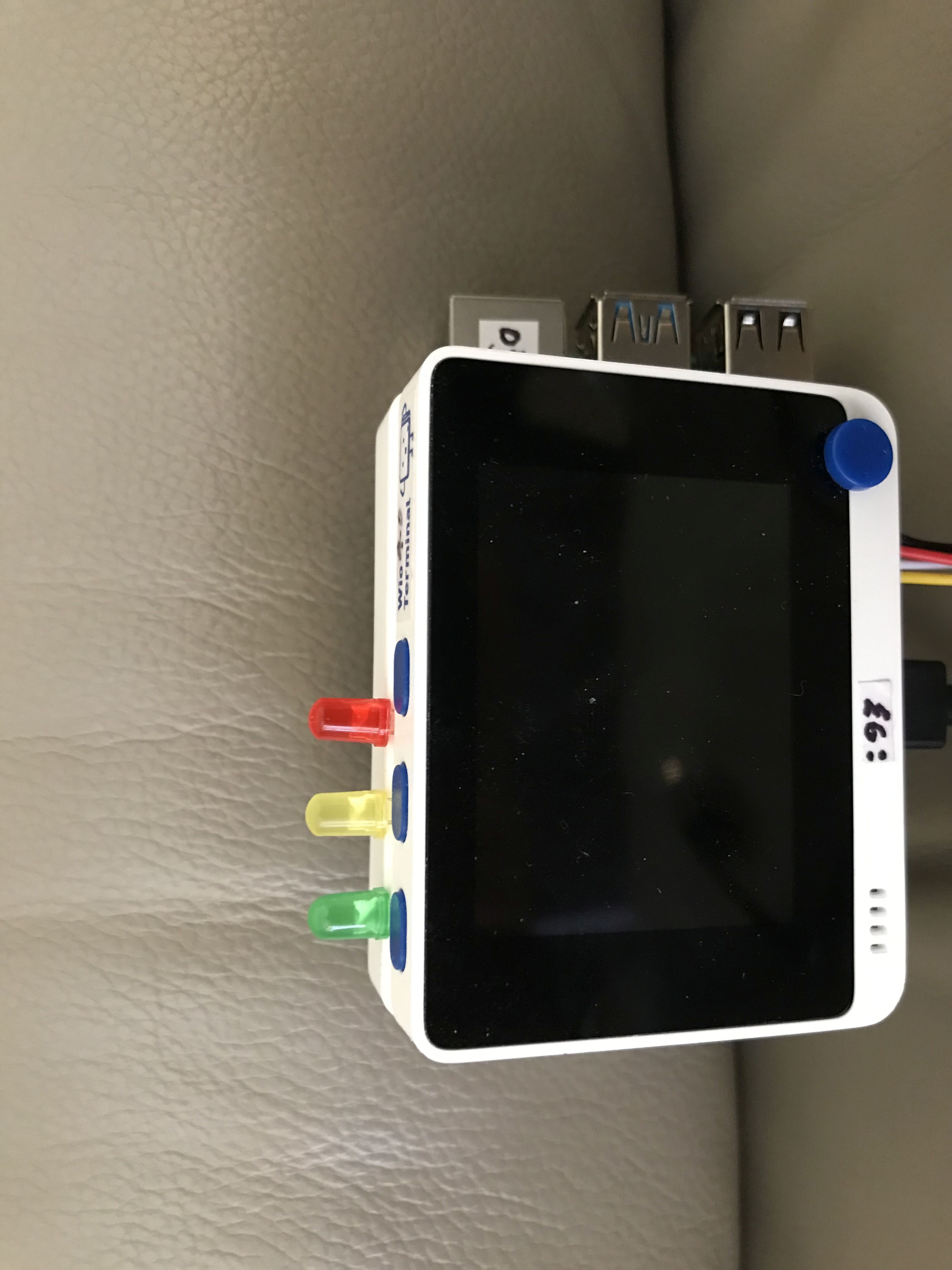
The "portrait" positioning of the Red, Yellow and Green LEDs on the left edge (or left side) resembles a 'traffic light". The buttons will convey the idea of Red on top (meaning "No") and green on the bottom (meaning "Yes").
Alternatively, the whole RPi/WioTerminal "block" could be oriented by 90 degrees putting the 3 LEDs and switches on the top, oriented like a "traffic light" if you tilt your head slightly to the right when viewing the LEDs on the top edge.
A schematic diagram of the Adafruit 4132 internal circuitry can be found on page 13 of Source 08 below.
When you see a boat approaching you, the Red light of the approaching boat is on the Right; the Green light of the boat approaching you is on the left. This is exactly how a modern mariner sees an approaching boat. The PiR2 can be considered to be approaching you with its Red light on the right. Its port side is red and is on the right. The starboard side of the approaching boat is green and is on the left. But on the mariner's own boat, of course, the red light is on his left when the mariner is facing forward. I've been told: "When docked, ancient Roman boats tied up with the pier (wharf or port) on the left because the man on the rudder always had his rudder fastened to the right side of the boat."
(To enlarge .....Click it)
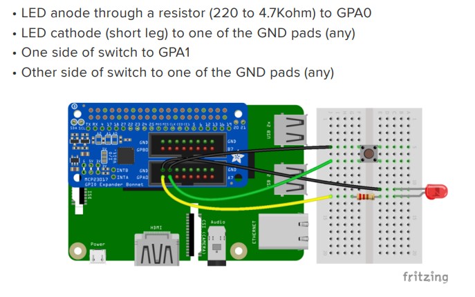
Adafruit 4132 LED Resistor Wiring (fritzing diagram)
To drive the LED by the Adafruit 4132, a resistor is needed. Its value can be anywhere from 220 ohms to 4k7 ohms, the higher values make the LED be dimmer.
(To enlarge .....Click it)
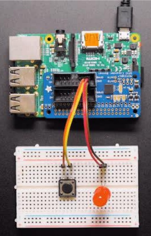
AdaFruit 4132 Mounted On An RPi
The above image shows the positioning of the Adafruit 4132 relative to the WioTerminal board. Current-limiting resistors are unfortunately NOT included in the image immediately above, but they should be included to keep the LED from burning out. and to lower the power consumption of the circuit.
Orientation of the 3 LEDs For the PiR2W
If the 3 LEDs are soldered in the normal way (with their bases very close to (i.e. flush with) the board), it will be impossible to
attach an RPi even if the Adafruit "GPIO Expander Bonnet" were equipped with a male and female header. But it is possible for the 3 LEDs to be given longer insulated leads. Then the 3 LEDs (with long insulated leads) can be soldered into the top 8 expansion DIO points of the Adafruit 4132 (having plated-through holes). Prior to soldering, the LED leads must be bent 90 degrees upwards (ie sideways to fit between the male pins of the 40 pin header). By doing this, the 3 LEDs will be sandwiched between pins connecting the GPIO Expander Bonnet and the device beside it. The GPIO Expander Bonnet can be placed between the WioTerminal and the "WioTerminal Chassis-Battery" or between the "WioTerminal Chassis-Battery" and the RPi. The LEDs will protrude outwards to the left (or upwards to the top) and will be situated very close to the 3 push-buttons on the edge of the WioTerminal. The other 2 to 8 Grove connectors of the PiR2 remain sufficiently exposed for use. For all this to succeed, an extra-long male to female 40 pin expansion header might need to be soldered onto the Adafruit 4132 or to the PiR2P.
Oriented in this manner, the three LEDs will appear as a typical "traffic light" on the left side of the WioTerminal. This would make the red LED be the upper LED. [ The Red LED will be near physical pin #18 which is GPIO24.] To protect the uSD card in the RPi, a base would need to be attached to the 2 existing bolt holes on the lower edge of the RPi. The next heading describes such a "base or stand". This orientation (with LEDs on the left edge) places the on/off
switch and uSD card of the WioTerminal at the bottom. The uJoySwitch will be in the top-right corner of the PiR2. This is not a major problem, the most important switches (the 3 push-button switches) are on the left hand side. Another important factor is that there will be no cables protruding out of the bottom.
Probably the 3 LEDs (and the other internal WioTerminal devices such as the buzzer) can be controlled by the RPi. To do this, the On/Off switch on the WioTerminal might need to be switched Off [but probably not].
A Stand (Base) For the PiR2W
The orientation (described above) of the Wio Terminal (seen in the rightmost image at the beginning of this article) will place the uJoyStick in the top right corner which changes the orientation of the directions of the 5 switches in the uJoyStick. Of course, the LCD screen will also need to be adjusted to a "portrait" orientation. All of these things are quite easy to adjust via software changes. The most difficult aspect of this new orientation is that both uSD cards; that of the RPi contain the (OS, software and data) and that of the PiR2 (containing the log data) will be on the bottom edge, subject to abuse as the PiR2W is moved from place to place. To protect these important uSD cards it will be necessary to elevate the PiR2 slightly by providing a small base. Of course, the addition of such a base (if it is heavy enough) will make the PiR2W more stable.
Most of the time, the PiR2W will be unattended; the 3 push-buttons and the 3 LEDs not requiring easy access. Occasionally, the user will need to access the On/Off switch and the uSD card in the WioTerminal. Fortunately, the PiR2W can optionally be positioned on its side with the 3 buttons and 3 LEDs facing somewhat upwards. A Z-shaped base designed expressly for the PiR2W will protect both the uSD cards and the 3 LEDs in this alternate orientation (shown below).
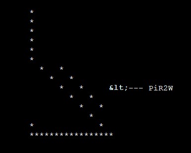
A superior orientation for the PiR2W might be by mounting it at 45 degrees on a "Z" type stand (as shown in a side view below.) The three joints are simple (3D-printed) hinged axle-style joints that are tightened together with wing-nuts. See the hinge-image below to better grasp this idea.
                        *
                        *
                        *
                        *
                        *
            hinge ->    o
                          *   *
                            *   *
                              *   *     <--- PiR2W
                                o   *
                                  *   *
                        *           *
                        *             *
                        o*******o*******o
The 4 pieces of the PiR2W would be mounted on the 45 degree sloping portion of the stand. They would face upwards
and to the right. The 3 buttons would be along the top edge of the PiR2W. The 3 LEDs would be visible (barely), located behind the 3 buttons. The uJoyStick would be in the bottom right hand corner (well positioned for right-handed users.) Wires would pass through the big square holes in the stand or to the side. All 8 of the Grove connectors would be accessible. The on/off button on the WioTerminal and both uSD cards are accessible on the left side. The seldom-used on/off button on the WioT battery would still not be very handy, being too close to the right side of the RPi board. A future camera might be mounted on the vertical part of the Z-base. This stand could sit on a desk (or table), but on a desk, the PiR2W might need a weight in its base for stability. The vertical edge of the base of the Z-stand and the top vertical part of the stand could be attached to a vertical surface like a wall. A small terminal block could be mounted on the wall (and be hidden by the stand). Small terminal boards exist with connectors or screw-type terminals to which wires can be attached. This version (or model) of the PiR2 seems to be a truly usable version!
To enlarge .....Click it)
Z-base at 45 degrees
The Hinge Pieces
The Hinge piece (shown below) will be 3D printed. I may use tinkercad to design them. It will take 6 of these hinges to create the above stand.
To enlarge .....Click it)
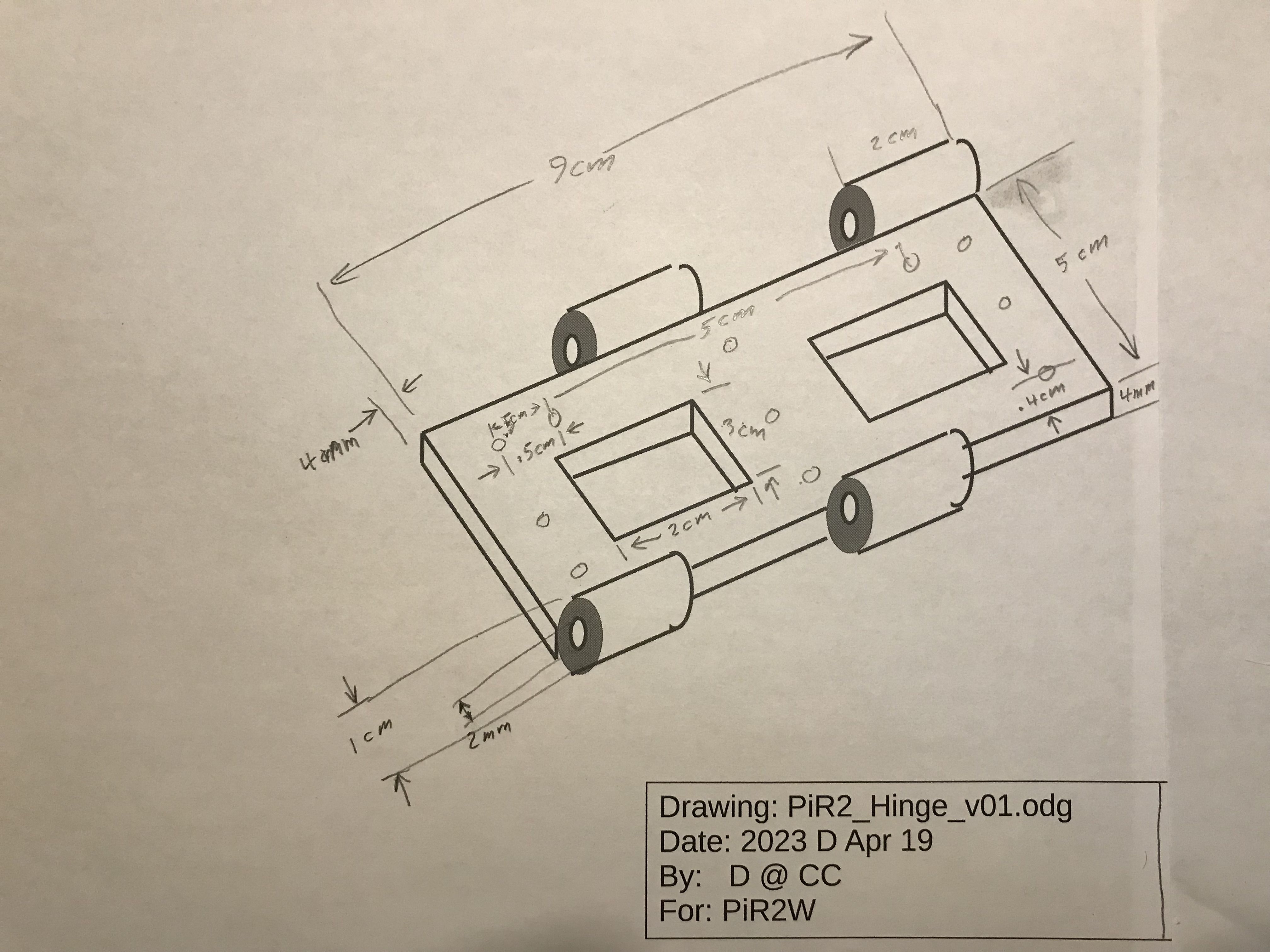
PiR2W Hinge Piece
Schematic of the PiR2P
The PiR2W was designed, thinking that the Adafruit 4132 could be equipped with both male and a female
header pins, but it was quickly discovered that the Adafruit 4132 is only shipped with a female header. This version
of the board was renamed the PiR2PAda and it can only be used with either the WioTerminal or the RPi
but not both. To function with both (or either), the author has created the PiR2P built on a Proto Board with
both male and female 40 pin headers.
(To enlarge .....Click it)
PiR2P built on a Proto Board
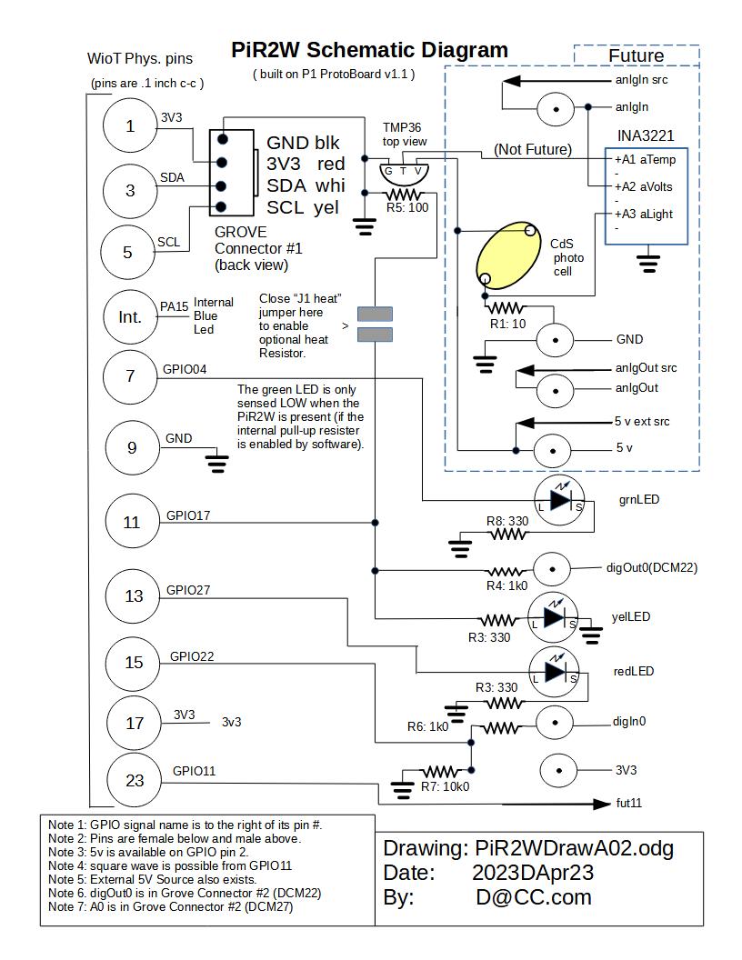
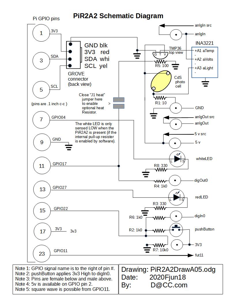
This schematic diagram is GPIO pin-compatible with earlier versions of the PiR2 which minimizes software
changes and testing. Note 4 on the above schematic mentions the sourcing of a square wave from the Raspberry
Pi. Source 19 describes, in detail, how the RPi can produce such a square wave.
Wiring Diagram of the PiR2P
(To enlarge .....Click it)
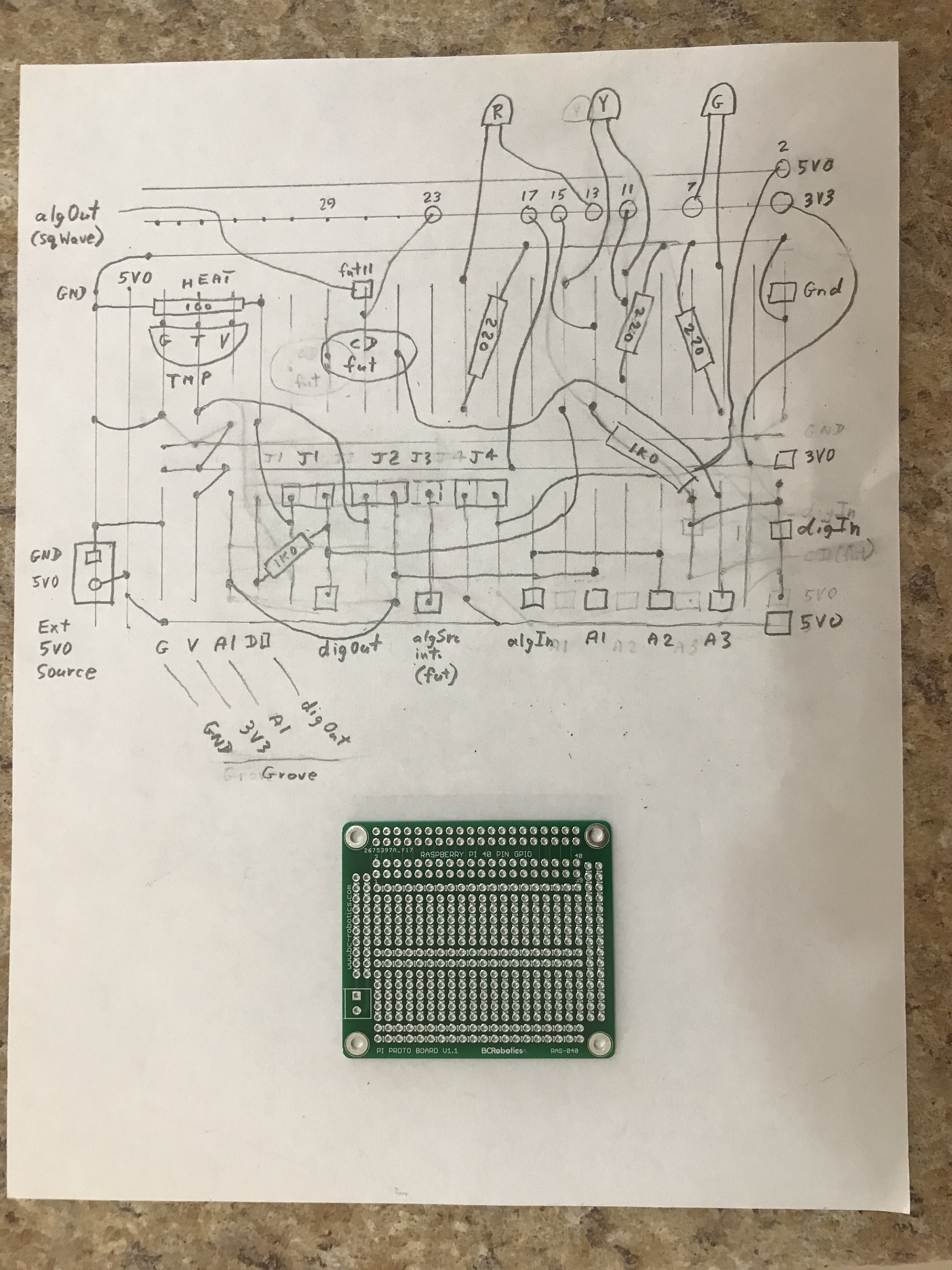
PiR2P Wiring on a Proto Board
The author apoligizes for the above early draft version of the PiR2P wiring diagram.
NOTE: Oddly enough, this whole PiR2P board is optional, because the only
      essential component is the external temperature sensor which
      connects directly to the WioTerminal via a Grove cable. Optionally, the
      TMP36 temperature sensor can be included on the PiR2P board.  This facilitates
      using this board for control-loop experiments and demonstrations.  The
      display on the WioTerminal greatly improves these demonstrations.

Note: A1, A2, A3 can be used for future algVoltage measurements by an INA3221.
The WioTerminal is wired to optionally measure A1. One Grove connector
     outputs A1 (to be measured by the WioTerminal) and digOut which
     is High when it is "calling for" heat.

digIn & digOut are future additions
digIn is read by GPIO phys pin 15
digOut can control an external relay to turn on Heat (like a thermostat)
     The high state of digOut is visible by both the Yellow led on the PiR2P
     and the tiny Blue led on the WioTerminal being lit.
     digOut and A1 share a Grove connector.

J1 - IN:  enables the Heat Resistor (100 ohms) near the TMP36
     OUT: disables the Heat Resistor (permitting GPIO12
          to drive both the yelLed and digOut

J2 - IN:  Connects the TMP36 (on board thermometer) to A1
     (Note J2 or J3 can be used, not both)
J3 - IN:  Connects (fut) algInInt (internal ambLight) to A1

J4 - IN:  Connects (fut) algInInt (internal ambLight) to A3

J5 - IN:  Connects External 5v0 to GPIO 5v0 (phys pin 02)
     OUT: Separates the external 5v0 from the GPIO 5v0
               (J4/J5 need to be changed on the PiR2P schematic)

A1 - This analog Voltage gets read by A1 on the WioTerminal Grove
     (or it can be read by a future INA3221).
A2 - Measures extAlg In (fut)
A3 - Measures CD0 (ambLight) (fut) or another analog source

   - Posts exist for GND, 3V3, 5v0, digIn, digOut, algSrcIn, algOut(Sq wave)
   - A connector exists for an external 5v0 DC Source
   - The 5 jumpers (J1, J2, J3, J4 & J5) need 3 Two-Pin jumpers.
   - A cable wired to PiR2P terminates in a Male Grove connector.
   - The PiR2P is designed to house a CD (light sensor) to measure
     ambLight via A1.
   - No pushbuttons exist because the WioTerminal already has 3.
Boards Making Up the PiR2W
(To enlarge .....Click it)
PiR2W mounted on the left edge of a RPi
           (Listed in order from Back to Front)
	RPi Zero W or another Pi board (optional)
	PiR2P with 3 LEDs on the Proto Board (optional)
	"Wio Terminal Chassis - Battery" (optional)
	Wio Terminal (LCD monitor, buzzer, the "top" 3 buttons and
                the Grove cable to the temperature sensor. )

     Note 1: A required base is not shown in the above image
     Note 2: The RPi is optional ONLY if the Python code can be fully ported to the WioTerminal
     Note 3: The PiR2P (or PiR2PAda) board is optional ONLY if the 3 LEDs will never be observed.
                Fortunately there is a tiny blue Led beside the WioTerminal's USB cable (on
		the opposite edge to the 3 buttons) that will be kept in the same state
		(On or Off) as the state of the Yellow Led. These 2 LEDs (blue & yellow)
		when ON show that the digOut (calling for Heat control) is High.
     Note 4: The Wio Terminal Chassis Battery is not needed if the whole PiR2W gets its
                power indirectly from the mains (110v) or from a substantial battery.
The simplicity of the PiR2W hardware coupled with the common use of MicroPython code makes a very feasible new combination. To describe it in more detail: the next model of the PiR2 will be comprised of the following:
A More Detailed Description of the PiR2W Boards
Shown below is a more detailed explanation of the PiR2W combination of
boards with their GPIO pins plugged together and with the "traffic light"
LEDs and 3 buttons on the left edge.

the RPi Zero W (with GPIO02 [pin 3] in the bottom left corner, with male GPIO pins)
the PiR2P with male & female GPIO pins and
    with 3 LEDs mounted on it (Red top and Green bottom).  There is also
    a digOut pin or wire from the PiR2P or from a Grove connector
    that is (optionally) High when Heat should be turned on by the PiR2P.
the "Wio Terminal Chassis - Battery" (with male & female GPIO pins)
the Wio Terminal (with its female GPIO02 pin at the bottom left corner)
    with the on/off switch on the bottom edge (not visible) beside
    the slot for a log file written to a uSD memory card (up to 16 GB).

Note 1: Simply remove the RPi to let the WioTerminal control the peripheral devices.
Note 2: GPIO02 [pin 3] is in the bottom left corner on the RPi oriented as above.
Note 3: The removable uSD memory card is on the bottom edge of the WioTerminal
        The On/Off switch will also be on the bottom edge of the WioTerminal
Note 4: Physical pin 37 [GPIO26] of the Adafruit 4132 should be avoided because
         it is not connected to any plated-through hole on the Adafruit 4132.
Note 5: The Grove cable will be on the right edge of the WioTerminal (visible in the image).
Note 6: The cable for the power for the RPi will be on the right side of the PiR2W.

The uSD card in the WioTerminal can be read (or written to) by either the RPi
or the Wio Terminal but not by both at the same time.

Hopefully, the uSD card on the WioTerminal will use the same MicroPython drivers as the
uSD card on the Cytron Maker pHAT board for the Raspberry Pi. If so, this will mean less
software development and/or testing.

The PiR2WL board will also have a functional CD photocell to measure ambLight.
Attaching the components together with a base
The 4 devices (listed under the upper heading) will simply be plugged together using their male/female sets of 40 GPIO pins. The uSD card on the WioTerminal will house the log file. A buzzer, 3 LEDs and a small LCD screen are available on the WioTerminal to communicate with the user. A Grove connector will accept a cable leading to a thermometer located in a refrigerator or freezer. Today the PiR2 uses WiFi to communicate with the world via a nearby router. In the near future, hopefully, the WioTerminal will successfully use Wifi. Until then, the WioTerminal will use this PiR2W device to monitor a refrigerator, a freezer and/or the ambient temperature with both an audible buzzer and a visible LCD monitor (both in the WioTerminal) providing alarm notifications.
Power and On/Off Switches
The complete PiR2W has 3 USB-C power connectors and 2 ON/OFF switches. One of these ON/OFF switches (the switch on the WioTerminal) also has a "Double Flick" action that is used to enter "FLASH" mode. The resulting combinations of all these switches is various "combinations and/or sequences" of powering the WioTerminal, WioT-Battery and the RPi. These 5 power-up scenarios present many, many options. When plugged into the RPi, it is very difficult to physically turn on/off the "Wio Terminal Chassis - Battery". To operate the on/off switch on the battery, I use a GPIO extender and a paper clip with a tiny 90 degree bend at the tip (shown below).
(To enlarge .....Click it)
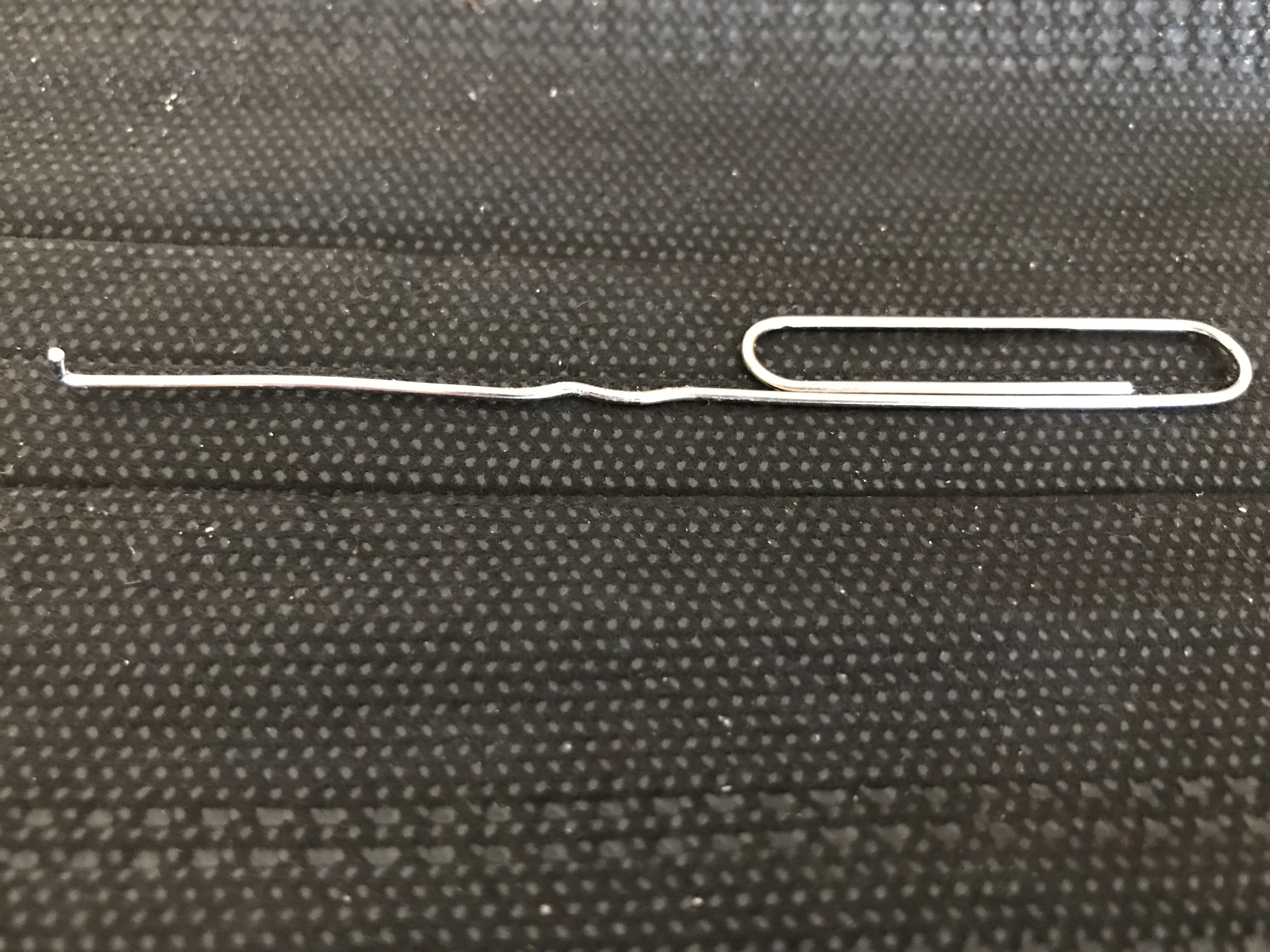
Tiny Tool for WioT Battery Power Switch
A plastic martini-stir-stick (with a tiny bulb on one end) might be an even better tool. Composed of plastic, not metal, it would avoid all possibilities of short-circuits.
Some interesting combinations/sequences of the switches are shown on Pages 1 and 2 below:
Notes: "!!!" means this is an unexpected situation, "B" means "Batt.", "Flicks" or "Fl" mean "2 quick flicks down",
       "n" means "no Batt.",  "RPi" means "Raspberry Pi",  "v" means "verified",  "WioT"is WioTerminal,
       "Done804" means "Done | 8.0.4" showing on the top line of the LCD while in FLASH mode.
        Normally "main.py | 8.0.4"    shows on the top line of the LCD when not in FLASH mode.
       "other"   means any other computer (Laptop, RPi, Mac/Apple etc) connected to the WioTerminal via a USB-C cable


Battery	On/Off	WioT On/Off	RPi	 USB-C	Led Indicators			WioT	RPi	Situation	Page 1
Switches 	Switches	GPIO	 Power	(battery) WioT		Vfyd	LCD	LED	Status
-------------	-------------	------	 ----	------	------------	----	---	---	------
na (no Batt.)	off		absent	 na	All Off			  v	dark	na	SINGLE WioT NO USB
na (no Batt.)	Off		absent	 WioT.	All Off			  v	dark	na	SINGLE WioT Sw:Off
na (no Batt.)	On		absent	 WioT.	Blue flashes, then Off	  v	main.py	na	SINGLE WioT ON w USB
na (no Batt.)	1:Off 2:Fl 3:On	absent	 WioT.	Blue 3 flashes, etc	  v	Done804	other	FLASH Mode via other

Off		On or Off	absent	 na	Red-Off	Blue-Off	  v	dark	na	No Batt, No USB, No RPi
Off		1:Off 2:Flicks	absent	 na	Red-Off	Blue-Off	  v	dark	na	No Batt, No USB, No RPi
On		Off		absent	 na	Red-On	Blue Off	  v	dark	na	WioT turned Off
On		Flicks		absent	 na	Red-On	Blue Flashes	  v	dark	na	WioT in FLASH mode
On		On		absent	 na	Red-On	Blue(Flashes,Off) v	main.py	na	WioT Normal Start-Up


Off		Flicks		present	 na	Red-Off	Blue-Off	  v	dark	Off

Off		Off		present	 na	Red-Off	Blue-Off	  v	dark	Off
1:Off 2:On	On		present	 na	R:On G:fla Blue(Fla,Off)  v	Fl,dark	Off
1:Off 2:On	1:Off 2:Flicks	present	 na	Red-On	Blue(Fla,On)	  v	dark	On


Battery	On/Off	WioT On/Off	RPi	 USB-C	Led Indicators			WioT	RPi	Situation	Page 2
Switches 	Switches	GPIO	 Power	(battery) WioT		Vfyd	LCD	LED	Status
-------------	-------------	------	 ----	------	------------	----	---	---	------
Off		Off		present	 Batt.	R:Off G:On Blue:Off	  v	dark	Off	ALL Switches Off
Off		1:Off 2:On	present	 Batt.	R:Off G:On Blue:Fl,On	  v	dark	Off	Seldom used
1:Off 2:On	Off !!!		present	 Batt.	R:Off G:On Blue:Fl,On	  v	main.py	On	Batt. On

On		Off		present	 na	R:On	Blue Flashes	  ?	dark	On	STANDBY in Flash mode
On		Off !!!		present	 1:n2:B	R:On G:On Blue:Off	  v	main.py	On	ReStart via USB

On		On		present	 na	R:On	Blue Flashes		dark	On	STANDBY
On		1:Off 2:On	present	 Batt.	R:On G:On Blue:Off	  v	main.py	On	ALL TURNED ON
On		2:Off 3:Fl 4:On	present	 1:n5:B	R:On	Blue Flashes	  v	dark	On	6:n RESTART
On		On		present	 1:n2:B	R:On G:On Blue:Off	  v	main.py	On	NORMAL
On		On		present	 Batt.	R:On G:On Blue:Off	  v	main.py	On

On		Flicks		present	 na	R:On G:Off Blue Flashes	  ?	dark	On
On		Flicks		present	 na	R:On G:Off Blue Off	  ?	main.py	On
On		1:Flicks 2:On	present	 Batt.	R:On G:On Blue:Flashes	  v	dark	On	FLASH MODE

On		Off !!!		present	 Batt.	R:On G:On Blue:On	  v	dark	On	RPi only
On		Off !!!		present	 RPi	R:On G:Off Blue:Off	  v	main.py	On	RPi w WioT
On		Off !!!		present	 WioT	R:On G:Off Blue:Off	  v	main.py	On	RPi w WioT

Some of the above combinations occurred without my knowing what caused them. :(

Note: "6:n" is the third last step of the full "WioT Restart Procedure" shown below.
           These steps will definitely take the WioT from any Mode into running main.py

The following complex RESTART Procedure works (without ending up in Flash Mode) . . . so follow it "to the letter"

0. Turn the "hard-to-get-at" Batt. switch ON (normally this is already the case)
1. Remove the USB-C power from the Batt.  (This might restart the WioT, but that's ok.)
2. Turn OFF the WioT switch
3. Flick the WioT switch down twice (puts it in FLASH mode, with the blue LED flashing)
4. It will have turned ON the WioT Switch automatically
5. Plug the USB-C power into the Batt.
6. Remove the USB-C power from the Batt. (exits FLASH mode & restarts)
7. Plug the USB-C power into the Batt. (to charge the Batt.)
     The WioT will restart & will run main.py (blue LED is Off)
8. The RPi has power when it has USB Power (or when it is connected via GPIO
     and any USB-C has power).
Ideally, the On/Off switch on the "Wio Terminal Chassis - Battery" will seldom need to be switched. Of course,
the uJoyStick and the 3 buttons and the 3 LEDs (on the edge) will provide a satisfactory user interface. The
power and Grove cables will seldom need to be changed. A stable base really does need to be found (or designed
and built) to support the PiR2W.
The Amazing and Simple Design of the WioTerminal!
(To enlarge .....Click it)
The PiR2W and RPi on a Little White Stand
The amazing WioTerminal (shown above) contains many of the ingredients needed by the PiR2 . . . so many that it seems to have been designed for this specific job. I wonder for how long an RPi Zero W (and the other internal WioTerminal devices) can remain powered using only the WioT Battery in the case of a Power Outage? A normal router usually fails immediately during a power outage. To mitigate against power outages, the LoRa communications method (also supplied by SeeedStudio for the WioTerminal) would become very attractive. I recently read that the WioT battery doesn't provide 3v3 . . . . and that this voltage conversion needs to be done by the Wio Terminal (it certainly can be done by the RPi). It remains to be seen if this voltage conversion presents a difficulty.
It seems quite possible that the WioTerminal might, one day soon, provide all of the functionality for devices such as the PiR2.
"Wio Terminal" Review by Hackster.io
I recently discovered a very technical analysis of the Wio Terminal at Source 13 by hackster.io . He cites keywords:
microcontroller, display, lcd, accelerometer and microphone
Dhrystone Benchmarks of the WioTerminal were between 200 Million Instructions/sec (MIPS) to 330 MIPS. He even mentions the following:
impressive projects: live-view thermal cameras, automotive dashboards,
home automation systems, retro gaming consoles, pocket oscilloscopes, and even an 'artificial nose' . He mentions that the "WioT Battery" adds:
-650 mAh rechargeable battery
-6 Grove interfaces
-4 analog/digital ports
-1 I2C port
-1 Uart port
For even more information, see Video Source 02 by CurryKitten.
A Remote Outdoor Air Quality Monitor Display
(To enlarge .....Click it)
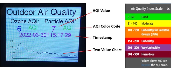
Wio Terminal for Air Quality Monitoring
This recent (2022) project (Source 07) sets up a Seeed Wio Terminal as a remote outdoor air quality display that shows ozone (O3) and Particulate Matter (PM2.5 and PM10) data. The Wio Terminal receives AQI data over WiFi by subscribing to live sensor data using MQTT with Machinechat's JEDI One IoT data platform. Arduino is used to implement the Wio Terminal application and JEDI One is installed and running on a Raspberry Pi 4.
Using ide.tinkergen.com on the "Wio Terminal"
This working, simple programming language exists and can be used for experimenting with the "Wio Terminal". (See Source 14.)
eRPC: Getting Started
This Getting Started User's Guide shows software developers how to use Remote Procedure Calls (RPC) in embedded
multicore microcontrollers (eRPC). The concept of and IDL file stored on disk is paramount. An IDL file is an
Interface and type Library Definitions file. The MIDL compiler will parse an Interface Definition File regardless of its extension, but the recommended extension is .idl . There is an eRPC generator tool, that uses the IDL files to generate some of
the shim code. The client side is the "primary core". The server side is the "secondary core". It is very important to
include the "unique name" of the function in every method, routine, function, folder and file that is created and/or
referenced by the eRPC mechanism.
In Source 23, in 2018, NXP Semiconductors published an "introduction to eRPC" complete with some examples. I hope that these examples
will show me how complicated it is to use eRPC. I intend to use eRPC running Python on the client and server cores. For example, I will use a Raspberry Pi (or a PC) to request that specific functions be run on a Raspberry Pico, a Wio Terminal or a Raspberry Pi. I plan to implement some very simple "throw" and "catch" pairs of Python routines called ixmRPC functions (Article 193 in Source 25). Each of these simple ixmRPC routines can, one day, be converted to a true eRPC mechanism. I will begin by using a serial USB transport, not I2C etc. My simplified eRPC "functions" will be core-specific and they will specify exactly which device is being used to accomplish the function (e.g. to read the temperature). The PiR2P must be able to be told which sensor (and which type of sensor) it should use to read the temperature. Its current thermometer options include: TMP103, TMP36 or SHT31.
This is the best article that I have found to introduce me to the overall concept of eRPC. It provides enough detail for me
to understand the process. But not enough detail to actually create code to interact with it. For programmers who are new
to eRPC, they should quickly read this article by NXP Semiconductors. I have started coding some RPC procedures and have run into many of the issues that have been addressed by eRPC.
The overall process is as follows:
The eRPC process uses c/c++ but the software implementing eRPC need not be written in c/c++ .
The resulting eRPC permits a client core to request that the server core perform an action,
    optionally returning a result.  The two cores (processors) are usually different. A communication
    protocol (transport) must be selected.  Options are:

    serial UART
    TCP
    I2C
    SPI
    etc

-a name is chosen for the function that will be sent from the client core to the server core
-the input/output parameters needed by the function are defined
-two shim (c/c++) procedures are generated: one for the client core and one for the server core
    This only needs to done once.  The resulting code can be used many times afterwards
    with different parameters.
-Each set of shim code must be loaded into the proper folder on each client & server machine
-The startup files, board-related settings, peripheral drivers and utilities must be present
-The necessary codec routines that are needed must be present
-The communication can be "blocking" or "non-blocking". Blocking means that the server
    will keep control of the thread until the function is complete.  Blocking servers
    do not use interrupts.  Blocking servers are dedicated to the job of performing
    each function one at a time, usually in a FIFO mode.  Blocking servers might
    become "hung" unless a "time-out" is built into the function.
-A type of CTRL-C is usually difficult (or impossible) for the client to send to a
    "blocking" server. However "blocking" functions are much easier to create (to code).
-Each request instance must be assigned an ID so that a returned result can be
    correlated with it. This is not necessary for "blocking servers" but should be
    done to simplify the coversion to "non-blocking" servers in the future.

-an instance using eRPC does the following:

-1. the client core "throws" a single request,
-2. the server core "catches" the request,
-3. the server core optionally "throws" back a result.
     Each result is identified (correlated) to the request.

-consideration of the handling of errors should be addressed

-the concepts or mechanisms used are:

-a) shim code
-b) data types
-c) codec
-d) data serialization
-e) performing the eRPC request
-f) deserialization of the result of the eRPC request
-g) creation of the expected data structure (optional if not a result )
-h) sending back the result (optional if not a result )

Note that the data being sent or received must reside in a folder.
Routines called "API"s are coded by the user.  An API is an "App Programming
     Interface". These APIs do not need to be in c/c++ .
The resulting eRPC functions are said to be "c-wrapped".
One of the main advantages of eRPC is that a single client core routine can be
     created for a specific function. But multiple server core routiness can be
     used, each in a different environment, to perform the function and return
     the result. It is very important to use consistent "eRPC function names".
The above is the author's (perhaps over-simplified) view of the overall eRPC mechanism.
The New Wio Terminal eRPC (embedded Remote Procedure Call) Firmware
salmanfarisvp of electro{Maker} has created a project at Web Source 17. His project describes eRPC.
(To enlarge .....Click it)
eRPC (embedded Remote Procedure Call)
About the project
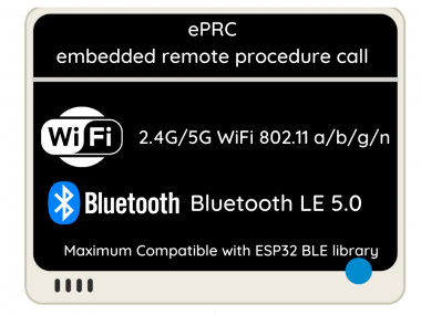
Seeed Wio Terminal has new WiFi and Bluetooth Firmware based on eRPC (a.k.a embedded Remote Procedure Call) that supports 5Ghz WiFi and BLE. ( Bluetooth LE 5.0 )
(To enlarge .....Click it)

eRPC (embedded Remote Procedure Call)
The eRPC (embedded Remote Procedure Call) is a Remote Procedure Call (RPC) mechanism used to invoke a software routine on a remote system using a simple local function call to invoke the Realtek RTL8720DN WiFi and Bluetooth Low Energy Functions.
The eRPC protocol is used to implement API calls between different architectures and different chips. In this software library, we mainly implement API calls related to Bluetooth and WiFi. It can communicate through UART, SPI, I2C and other interfaces. [But] we use UART to communicate in this software library.
The old AT-Command Wi-Fi firmware and related libraries will not work with Bluetooth at the same time and are getting [deprecated?] but after upgrading to eRPC you can use that ["that" meaning "eRPC"?].
eRPC Based Firmware Features:
-Maximum Compatible with ESP32 wifi library
-Dual Band 2.4Ghz / 5Ghz Wi-Fi (802.11 a/b/g/n)
-BLE / BLE 5.0
-WiFi and BLE low power consumption
As part of the eRPC Firmware, Seeed provided two libraries
Seeed_Arduino_rpcBLE
Seeed_Arduino_rpcWiFi
salmanfarisvp writes:
"The rpcWiFi software library calls Seeed Arduino rpcUnified to implement WiFi and BLE function compatibility with Arduino-ESP32. To reduce the [storage space] cost of using the software, you can import your favourite ESP32 wifi app and BLE app directly, with minor changes, and then use it. You'll find that your favourite ESP32 app has 5G features and has BLE5.0 features, runs on ARM and other architectures".
Source 20 (at pypi.org) describes the eRPC Python Infrastructure in more detail. See the Help submenu (at top) for the topics: Basics, My Account, Integrating, Administration of projects on PyPi, Troubleshooting and About. There is a github wiki about eRPC at Source 21. Especially good is the introduction "What is the eRPC?" at github in Source 21.
In Source 22 (at github) eeumairali describes an issue (and a solution by MichalPrincNXP on 2021ISep24 ) while using eRPC on a Raspberry Pi (with Python) as a client and a PC as the Server. He compares communicating by "serial rs232" with "erpc using TCP". TCP is apparently much faster than serial.
The web page author has not yet implemented eRPC as of 2023DApr23.
ixmRPC Heading has been moved to Article 193
UPDATE: WiFi and BlueTooth Are Now Operational
Refer to Source 15 where, as of 2023AJan19, Seeed Studio has documented the necessary steps to make WiFi and BlueTooth function correctly on the WioTerminal. The author has not yet done this and has NOT yet tested WiFi and BlueTooth on the WioTerminal. This is indeed very good news, if in fact, it works properly.
Note that Video Source 03 is one year old and does NOT represent the current situation as of 2023DApr22.
The Future PiR2W Controller
Future extensions of the PiR2W might include:
- improved communications using LoRa or IR between PiR2W devices
- an improved speaker (better than the buzzer in the WioTerminal)
- a mini-speaker connected via BlueTooth
- a real keyboard and/or mouse via BlueTooth
- a "pause logging" command to permit changing the uSD
card in the WioTerminal "while operating a "fuel gauge"
to show the status of the WioTerminal "battery"
- a tiny camera
- using the LCD display as a small monitor with a Command Line
or as an ultra-tiny monitor for the Raspberry Pi.
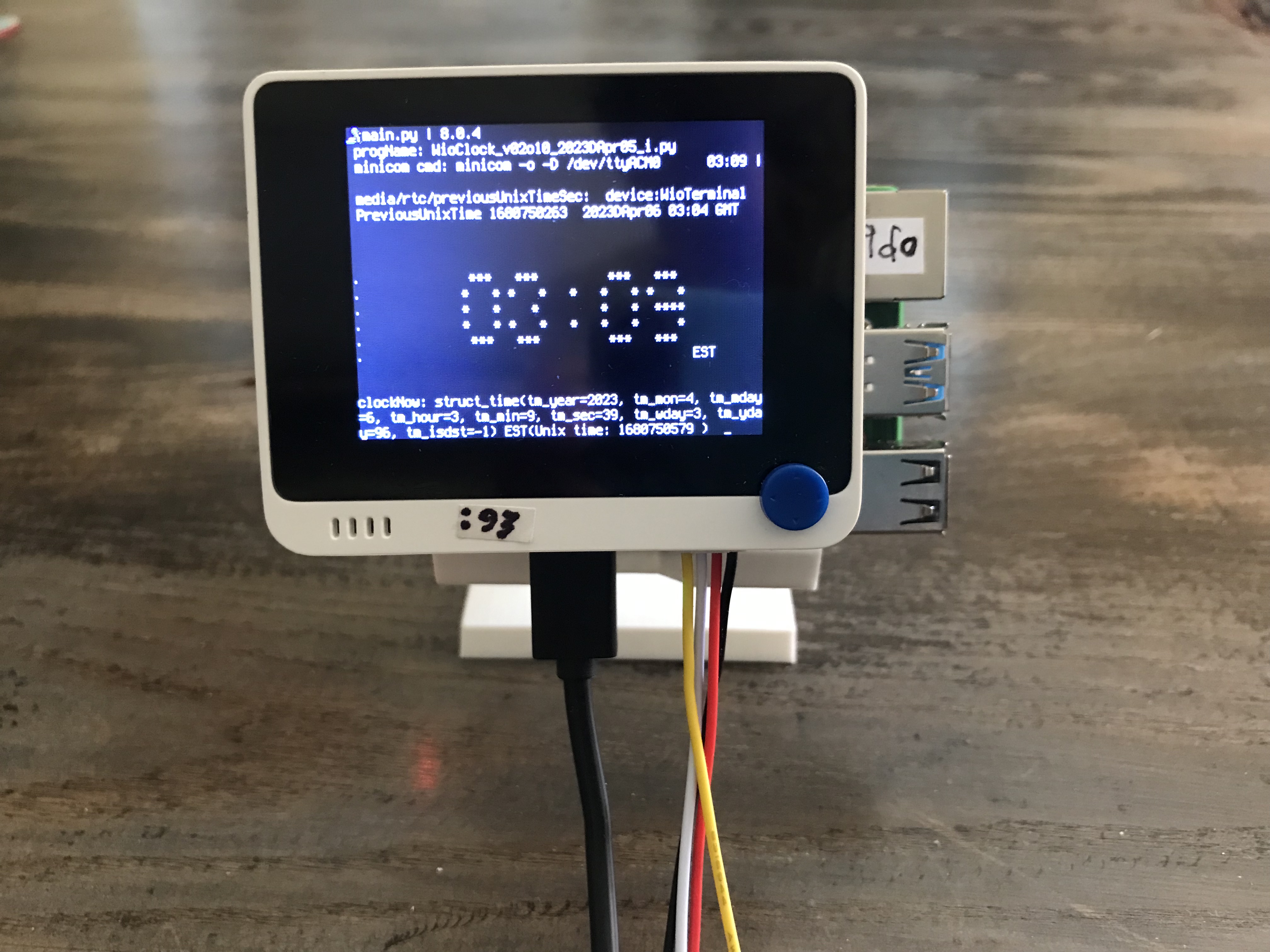
- inclusion of a clock displayed on the LCD via software
- inclusion of a 3rd USB charging port (perhaps located in the base)
to charge and monitor iPhones and/or other devices overnight.
- inclusion of a cooling fan in the base of the PiR2W
especially to cool a hot Raspberry Pi model 4 board.
- inclusion of a terminal strip mounted inside the base.
Source 26 is the 2023 May edition of the Raspberry MagPi periodical #129. It showcases a few
devices that contributers have created (or purchased) for DIY Home Automation. The ComfilePi,
at first glance, looked like a Wio Terminal. But, upon closer scrutiny, was actually much
bigger, more powerful and more expensive (with a price tag exceeding US$ 298.00. However,
it prompts many ideas for things to do with the smaller Wio Terminal costing 1/10 the price.
The Adafruit Product # 3577 (shown below) is an inexpensive (US$ 2.50) Pi-Hat that is sold without any 40 pin connector. It
is a smaller alternative to the BC-Robotics ProtoBoard, if only the 3 LEDs need to be added.
(To enlarge .....Click it)
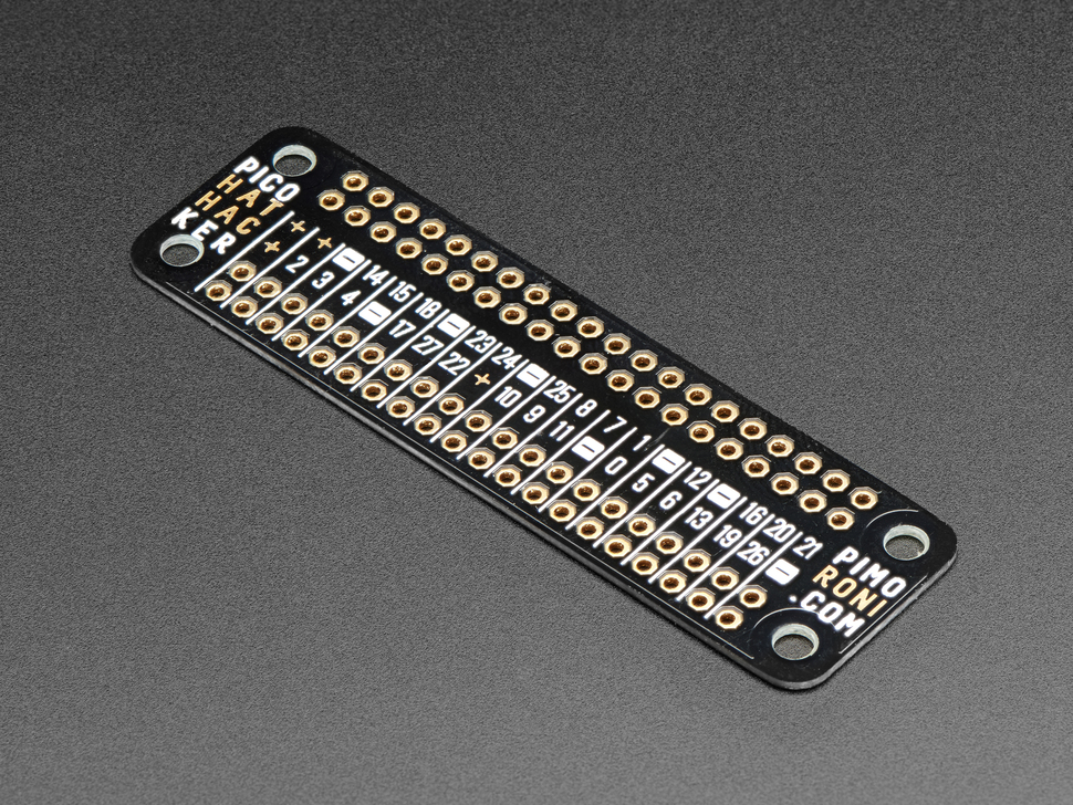
Adafruit 3577 Pico HAT Hacker
Conclusion
The hardware for the PiR2W is very easy to prepare and assemble. Changes to the software will require the most effort (by me). A suitable Z-base for the PiR2W will probably be feasible using a 3D printer. This is indeed the simplest (to date) model of PiR2 to put together. If the PiR2 software can be fully ported to the WioTerminal, there will be no need for the Raspberry Pi computer. If so, the WioTerminal will do everything. Once WiFi is truly operational on the WioTerminal, the PiR2W will even interact with the www.MehInCharge.com (Source 17) website created by the author. At Source 17, the "www" link redirects to the MehInCharge website, the non-www link takes you to my "Meh In Charge" article 128.
In fact, the WioTerminal may include everything necessary to function as a PiR2W, without even needing the PiR2P hardware board nor the Raspberry Pi . . . . Just the SHT31 temperature sensor with Grove cable (US$ 9.90). If so, the Wio Terminal is truly AMAZING !!!
This program, pir2w.py , and the new PiR2W device, by David @ ColeCanada.com, are works-in-progress as of 2023DApr15.
This article, by D@CC, is of course, also a work-in-progress as of 2023DApr24.
Other Related Thoughts
		WARNING: Source 27 is infected with a virus from site: URL:Blacklist.
		Thankfully, my free Avast anti-virus checker catches and eliminates it.
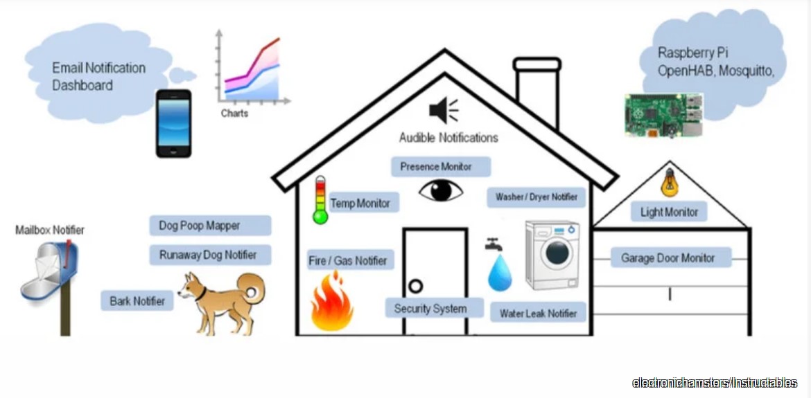
Source 27 describes a low-cost Uber Home Automation project by Marinel Sigui. It uses both a Raspberry Pi and an Arduino working together as shown below. My PiR2 system is simpler, but the Uber House Automation project is certainly better documented.
(To enlarge .....Click it)
Uber Home Automation
The Uber Home Automation system is a complex project requiring little or no software development. It's hardware includes a Raspberry Pi, an Arduino and a smart phone. It uses home-made sensors and actuators (soldered together by the home owner). It makes use of the openHAB community project at Source 29. This major project is not for the faint of heart.
End of Article (Sources Follow)
Sources
Video Sources
Video Source V191:01:www  Exploring the Wio Terminal ( 1:14 min)
by Seeed Studio in 2021
Exploring the Wio Terminal ( 1:14 min)
by Seeed Studio in 2021
Video Source V191:02:www  Exploring the Wio Terminal ( 15:00 min)
by CurryKitten in 2022
Exploring the Wio Terminal ( 15:00 min)
by CurryKitten in 2022
Video Source V191:03:www
WIO Terminal WIFI Issues -2 videos( 10:46 min) 1-2 YEARS OLD
by Lakshantha in 2021AJan00
Video Source V191:04:www
WIO Terminal Seeed Studio RPi 4( 10:46 min) 1-2 YEARS OLD
by leepspvideo 2020ISep06
Video Source V191:05:www
The New Wio Terminal eRPC Firmware, ends with
WioTerminal Classroom with IoT #1 Video (18:57 min)
by Lakshantha Dissanayake 2020KNov11
Web Sources
Web Source S191:01 www  Grove Components for PiR2D ver F
by David KC Cole on 2021AJan 11
Grove Components for PiR2D ver F
by David KC Cole on 2021AJan 11
Web Source S191:02: www PiR2A2DrawA05.jpg Image
by D@CC on 2020FJun 18
PiR2A2DrawA05.jpg Image
by D@CC on 2020FJun 18
Web Source S191:03:www
typing_3_mp3.txt  by D@CC of ICH180RR on 2023DApr07
Web Source S191:04:www
SHT31 Datasheet (zipped)  from Seeed Studio on 2022EMay16
Web Source S191:05:www
(Article 143) Figure 3 "Above PiR2A2 Main Components Layout (to scale)" on p12
by David Cole on 2020 F Jun 19
Web Source S191:06:www
wioClock_v02o11_2023DApr05_py.txt (my 3rd Wio program )
by D@CC of ICH180RR on 2023DApr08
Web Source S191:07:www
A Remote Outdoor Air Quality Monitor Display
by Scott RaekerM of DigiKey on 2022 C Mar
Web Source S191:08:www
Adafruit GPIO Expander Bonnet (4132)
at Mouser Electronics on 2023 D Apr 14
Web Source S191:09:www
Grove-Temp & Humidity Sensor (SHT31)
from Seeed Studio on 2018FJun01
Web Source S191:10:www
Comprehensive List of PiR2D references
by David Cole on 2023 D Apr 14
Web Source S191:11:www
Pi: Wio Terminal for Raspberry Pi (186.html)
by David Cole on 2023 D Apr 14
Web Source S191:12:www
Pi: PiR2A Area Controller Prototype (139.html)
by David Cole on 2020 E May 03
Web Source S191:13:www
Hands-On with the Wio Terminal
by Gareth Halfacree of IoT on 2020
Web Source S191:14:www
Experimenting with the Wio Terminal
by Robocraze in 2022
Web Source S191:15:www
Seeed Wiki: Wio Terminal - WiFi & BlueTooth Fixed
by Seeed Studio on 2023DApr22
Web Source S191:16: www
PiR2WDrawA02.jpg Image
by D@CC on 2023DApr23
Web Source S191:17:www
The New Wio Terminal Erpc Firmware (links to V191:05)
by salmanfarisvp of electro{maker}
Web Source S191:18:www
Pi: MIC - Meh In Charge .com (128.html)
by D @ CC of ICH180RR as of 2021DApr16
Web Source S191:19:www
Pi: . . . produce a square wave . . (pg 14 in S143:06)
by D @ CC of ICH180RR as of 2020FJun13
Web Source S191:20:www
eRPC Python Infrastructure (erpc 1.10.0)
by NXP and MichalPrinc as of 2023AJan19
Web Source S191:21:www
eRPC wiki at github
by Dusan Cervenka ( nxa14949 ) as of 2018DApr13
Web Source S191:22:www
Basic example of python and c #204
by eeumairali at github as of 2021ISep22
Web Source S191:23:www
eRPC Getting Started User`s Guide
by NXP Semiconductors as of 2018EMay00
Web Source S191:24:www
ixmRPC Pushbutton V01.00
by D@CC as of 2023DApr24
Web Source S191:25:www
A&C: ixmRPC (eRPC lite) Remote Procedure Calls (193.html)
by D @ CC of ICH180RR as of 2021DApr28
Web Source S191:26:www
DIY Home Automation
by MagPi on 2023EMay00
Web Source S191:27:www
Intro: the RPi Project That'll Automate Your Whole House (WARNING: has a Virux)
by SlashGear on 2023KNov13
Web Source S191:28:www
Uber Home Automation
by Electronic Hampsters Erix Tsai in Circuits on 2023KNov13
Web Source S191:29:www
About OpenHAB & a demo
by the openHAB Community before 2023KNov13
WebMaster: Ye Old King Cole
There is a way to "google" all the part-numbers, words and phrases in all my articles.  This  "google"
search limits itself ONLY to my articles. Just go to the top of "Articles by Old King Cole" and look
for the "search" input box by freefind.
Date Written : 2023 D Apr 15
Last Updated : 2023 K Nov 20
All rights reserved 2023 by (c) ICH180RR
saved in E:\E\2022\DevE\MyPagesE\Globat\ePhotoCaption.com\a\191\191.html
backed up to ePhotoCaption.com\a\191\191_2023EMay05.html
Font: Courier New 10 (monospaced)
/191.html
 by D@CC on 2020FJun 18
  PiR2WDrawA02.jpg Image