Pi: New Raspberry Pi Products eg Pi-400 c2021 (151)
This is a Work-In-Progress
Keywords
HDMI-1 Pi400 Pi-400 "Kensington Lock" K-Lock "Compute Module" CM3 CM4 "Raspberry Pi Pico" Pico
PIO BootSEL PiR2_Pico Pir2_Pico HC 74HC132 SN74HC Micro-Otthon "BBC micro:bit" uuid CID M.2 CM4
"Maker Nano RP2040" Cytron SN74AHC541N "Maker Pi Pico" Neopixel Qwiic Grove Piunora eMMC Cortex-A72
"Bluetooth 5.0" M.2 B-Key IOVDD 0GP00 PCF85063AT RPI-400 Chromium "CM4 Components"
Which physical HDMI connector is HDMI-1?
Consider booting up a Raspberry Pi-400 with the Linux OS and with only one cable plugged into an HDMI connector on the Raspberry Pi. The OS will discover the "live" link to the HDMI TV and will "label" it as HDMI-1 in all messaging to the user. During the boot process, "HDMI-1" will flash in the top right corner of the window. After the OS has been fully loaded, if the cable is physically moved to the "other" physical HDMI connector, "DVI1" will flash in the top right corner of the window. Usually, initially, the DVI1 screen (window) will be fully dark, but a mouse click will display (only) the Desktop folder. A Right-mouse Click will bring up the Desktop Panel subwindow with a submenu line labelled "Panel Appearance". Selecting this will display the main HDMI-1 window. If the Taskbar does not appear, click the mouse to bring up "Panel Appearance", then change the TaskBar to HDMI-1 This main HDMI-1 window will display the TaskBar and Desktop. Clicking on the Globe will start up Chromium. Chormium will take up to 10 seconds to start up and the Chromium window will appear.
The author plugs his HDMI cable into the connector furthest from the USB power connector. Doing this causes the OS to call it HDMI-1 and the OS calls the other physical HDMI connector DVI1. The OS will refer to its "unconnected" window as HDMI-2.
RPi Issue - Chromium unusable on the physical HDMI-0
However Chromium has its own mind. Chromium always displays to the physical HDMI-1 Connector. If you plug the HDMI cable into the physical HDMI-0 connector, the OS can be configured as mentioned above, but Chromium will not work. Clicking on the globe icon on the Taskbar will cause an empty window to be seen to be dynamically shrunk down to a point on the monitor. The author has not found a solution to this issue, other than connecting the physical HDMI cable to the HDMI-1 physical connector (the connector furthest from the USB power connector). Further investigation leads me to believe that Chromium displays onto the HDMI port where the TaskBar is sent using the subwindow shown below. If the reader finds this confusing, plug your HDMI cable into the HDMI-1 connector, furthest from the USB Power connector to avoid this issue.
(To enlarge .....Click it)
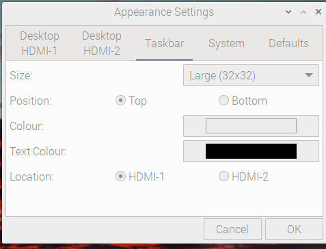
Appearance Taskbar subwindow
For more RPi Issues and solutions, see Source 22 which is Article 170 Pi: Useful Raspberry Pi Device Family Terminal Commands (170.html). Also see Source 21 which is Article 150 IT: Software Problems and Solutions (150.html).
Introduction
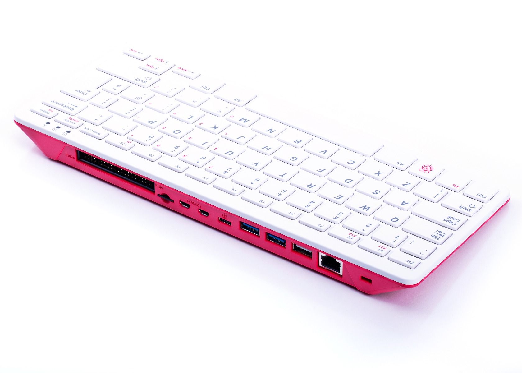
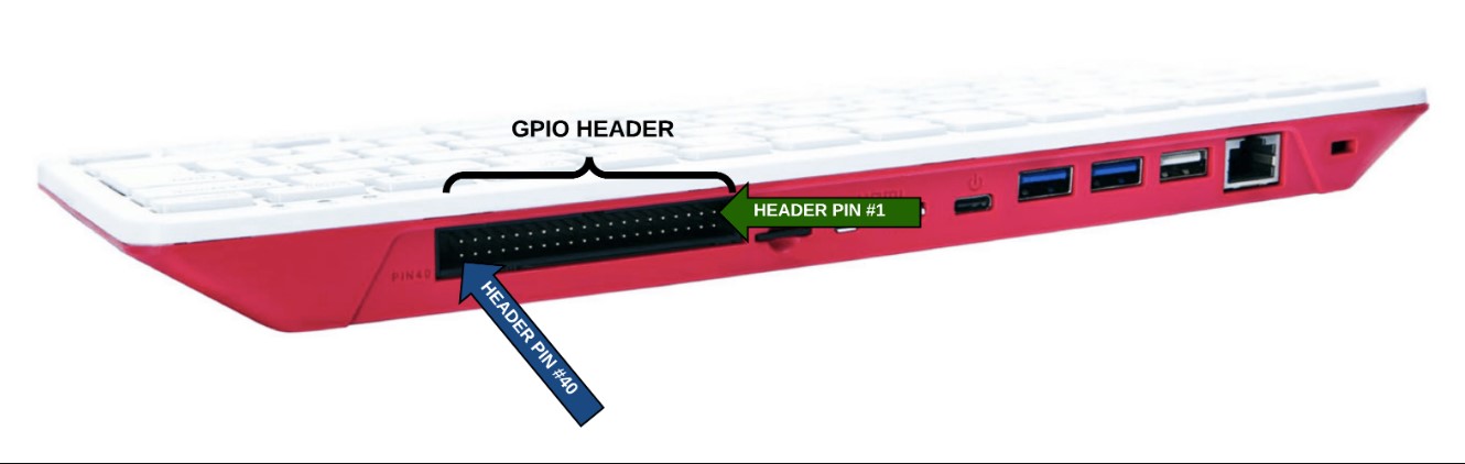
The RPI-400 (shown above) Kit is a PC in a keyboard. Anounced in 2020, it comes as a kit which costs US$100.00 and contains a Model 4 Raspberry Pi computer (including 4GB of RAM) with accessories that are ready to operate when you receive it. All that is needed is a WiFi or Ethernet connection, a microSD card and a TV set. Refer to Source 1 for more details. For those who already have a keyboard, mouse and a Model 4-compatible 5v0 power supply, a less expensive RPI-400 (not called a Kit) is available at a lower price of US$70. Users have complained about the lack of the following devices: a camera connector, a display connector and an audio-out jack on the RPI-400. I would have appreciated the inclusion of an I2C Grove connector (although I will try to add one in the future). The RPI-400 incorporates 2 x USB 3.0 ports and 1 x USB 2.0 ports plus a huge internal heat sink which eliminates the over-heating problems normally encountered with the Raspberry Model 4 boards. Refer to Source 7 for a full RPI-400 product brief in PDF format.
Compute Module
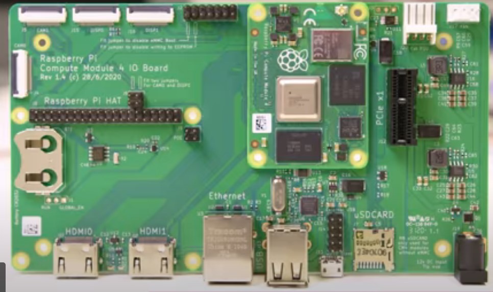
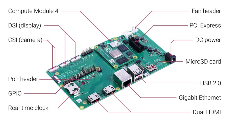
A Compute Module 3 based on the Raspberry Model 3 already exists. Soon after the announcement of the Raspberry Pi-400, a Compute Module 4 Lite (Source 2) was announced which is a very small board that contains all the electronics of the Pi Model 4 (including 1 GB of RAM) except the IO connectors. This board is called the Compute Module 4 Lite and costs US$25 . It was designed to permit PC manufacturers to inexpensively make use of the Raspberry Pi Model 4 by only providing a subset of the IO electronics needed for their particular application. Raspberry also announced a Compute Module 4 IO Board (costing US$35) on which the Compute Module 4 Lite can be mounted (as shown below). The Compute Module 4 I/O board includes IO facilties such as Ethernet, Wifi, Bluetooth and camera interfaces. It can be powered by 12v or 5v0 power supplies. The applications for the Compute Module 4 Lite would often be unattended and therefore it doesn't require a keyboard nor a mouse. As can be seen in the photo below, the 40 GPIO pins point upwards. Unlike other Raspberry Pi models, this board allows for an on-board CR2032 battery (to avoid the loss of the current time in the PCF85063AT RTC) and it provides a PoE header to enable it to receive power from the RJ11 Ethernet cable. A standard (non-micro-USB) DC connector exists to allow off-board DCpower. When 12v power is supplied, an on-board regulator provides 5v and 3v3 volt power to the board. A header for a 12v cooling fan is provided; accompanied by a tachometer to read the speed of the fan. More details about the cooling fan are provided below the photos. A red and a green LED are available to maintain compatibility with the Raspberry Pi 4, Model B. The Compute Module 4 Lite is the small add-on board with 4 nut and bolt holes.
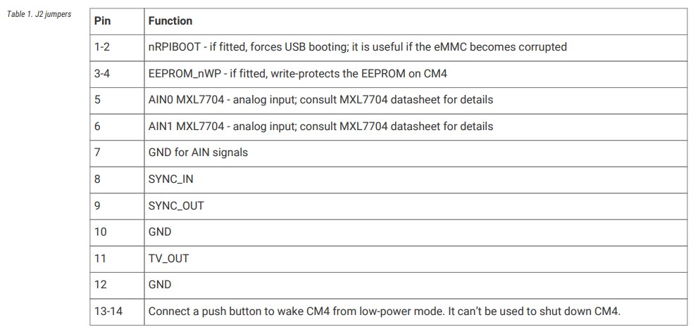
On the far right image above, a pin-out list of the CM4 J2 external/jumper pins is provided. The J2 is located immediately to the right of the two DSI (display) connectors at the back center of the CM4 board. Many of the features of the Compute Module 4 IO Board do not exist on other models of the Raspberry Pi Model boards. Most are desirable features but their inclusion would drive up the cost (and hence the selling price) of the Pi boards. Therefore, any Raspberry user is advised to purchase at least one of this board (and the Compute Module 4 board). Doing so should make a Raspberry Pi owner's life much easier. Some of these features are described below:
Cooling Fan
This connector supports standard +12V FANs with PWM drive and tacho output. An EMC2301 controls the fan via I2C.
The mating connector is part number Molex 47054-1000 or similar. The +12V power for the fan comes from the +12V input and
isn't regulated.
TIP
To enable the I2C bus to the fan controller you will need dtparam=i2c_vc=on set in config.txt . The fan controller then
will be on i2c-10 address 0x2f ( 7bit address)
Micro USB connector
The micro USB connector is designed to enable the CM4 to be updated via rpiboot. When a micro USB cable is plugged in,
the USB hub is automatically disabled, so the CM4 USB 2.0 port becomes a USB device. This exact functionality is unclear.
AIN0 and AIN1
These 2 pins on J2 are/were connected to an internal MXL7704 for power control. Apparently they are NOT connected to any Analog-Digital-Converter (ADC).
Raspberry Pi Pico
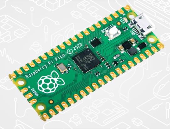
In early 2021, the Raspberry Foundation announced a "bit-banger" micro-processor board called the Raspberry Pi Pico (Source 3) selling for US$4.00 (shown in the photo below). This board is NOT compatible with the Raspberry Pi boards such as the the Pi models 2, 3 and 4. This Pi Pico board does NOT run the Raspbian operating system. It does contain a new proprietary Raspberry IC called the RP2040 which has a dual core Arm processor chip with 264KB of internal RAM, 2 MB of on-board flash memory and support for 16MB of off-chip flash memory. Current photos of the Pi Pico show a production date of 2020 although the Pi Pico was announced in early 2021. The RP2040 IC can be purchased by itself for companies (such as Adafruit) who are designing their own boards to compete with the Pi Pico.
The RP2040 also has a unique bank of PIO processors. The IO of each of these PIO processors is controlled by its own "machine-language" programs resulting in powerful "bit-banging" capabilities. Each PIO can be controlled by its own 32 word processor memory. The PIO instructions operate independantly of the Arm processors on the chip. There are 8 different instructions (listed below) for the PIO. Each instruction is accompanied by multiple parameters:
The 8 PIO Instructions
- 0 JMP
- 1 WAIT
- 2 IN
- 3 OUT
- 4 PUSH
- 5 PULL
- 6 MOV
- 7 IRQ
- 8 SET
Refer to the 2.5 hour video at Video Source 1 for a more complete description of the RP2040 and the PIO instructions.
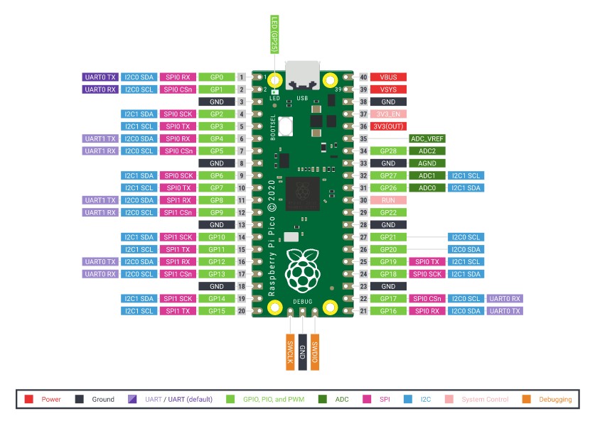
The Pi Pico has a wide range of GPIO pins whose pin-outs and signals are not compatible with the Raspberry Pi GPIO ports. Unlike the Raspberry Pi, the Pi Pico board has 3 12-bit Analog to Digital converters (ADC). It also has the following capabilities:
- 26 x multi-function GPIO pins
- 2 x SPI, 2 x I2C, 2 x UART, 3 x 12-bit ADC, 16 x controllable PWM channels
- Accurate clock and timer on-chip
- Temperature sensor [probably in the RP2040 IC to detect its operating temperature]
The Pi Pico also has an on-board USB-1.1 port that can be used to initialize and/or control the software in the Pi Pico. Unlike the Arduino, it has a clock and supports the Micro-Python software (which is a subset of the industry-standard Python software language). Wi-Fi connection is not needed for the Pi Pico to operate resulting in Micro Python not having access to the many Python code libraries available on the Web. The 2MB memory of the Pi Pico can be easily initialized by holding down an "Initialize" push-button during power-up. After power-up, the Pi Pico accepts terminal commands via the USB-1.1 port. Such commands are sent to the Arm micro-processor. When suitably initialized, the Arm micro-processor can interpret the terminal cmmmands as Micro-Python code. Different initialization software supports Circuit-Python or C/C++.
The Pi Pico is designed to receive its power from the 1v8 to 5v0 line on the USB-2 port. The Pi Pico runs on 3v3 logic by automatically raising low voltage power supplies to 3v3 or reducing 5v0 supplies to 3v3. This means that the power can even be provided by Lithium batteries.
The Pi Pico is shipped with castellated pin-outs. These castellated pin-outs permit the Pi Pico to be easily soldered to other boards without the need for any physical pins on the Pi Pico (although plated-through pin-holes do exist on the Pi Pico). Clearly, the Pi Pico is designed to be operated either by itself or in conjunction with a more powerful processor located on the board onto which it is soldered. A single LED on the Pi Pico can be controlled by user software.
Sparkfun provides a brief Youtube video introducing the Pi Pico (see Video Source 2). See more about the Pi Pico (in Video Source 3). A very detailed 636 page RP2040 datasheet can be seen at Source 8. The Pi Pico board is designed to give the user access to much of the functionality of the RP2040. The title of the Official Raspberry Pi Pico Guide in Source 10 is "Get started with MicroPython on Raspberry Pi Pico". This is an on-line updated version of the manual that comes with the Pi Pico. It contains the most up-to-date corrected version of the manual.
Reading the BOOTSEL as a regular PushButton
It is possible to read the BOOTSEL button (on the Pi Pico) as if it were a regular PushButton. This is somewhat complicated, but is possible. For more information see Source 11 which includes an example in "C" code. This example turns ON the small on-board Green LED when the BOOTSEL button is depressed. It is complicated because interrupts must be turned off temporarily and the Chip Select must be set to Hi-Z.
Creation of the Future PiR2_Pico based on the Pi Pico
It is the intention of the webmaster to create a PiR2 controller (named the PiR2_Pico) based on the Pi Pico. Compared to its competition, the main deficiency of the Raspberry Pi is its lack of Analog Input pins. Therefore the Pi Pico will be used by many to make use of the ADC capability (of the Pi Pico) to add 3 Analog Inputs to the Raspberry Pi. This can be done by soldering 6 female pins to each side of the Pi Pico. These should be physical pins 5 to 10 and physical pins 31 to 36 on the Pi Pico. On one side, these pins provide access to A0, A1 and A3, 3v3 and ground. On the other side, they are IO pins GP3 through GP7. The main intention is to use the USB to read the Analog Input lines. The Pi Pico will be queried as follows: The Raspberry Pi will send it a short character string e.g. "0A0" following by a CR-LF. (The initial 0 is the address of the first PiR2_Pico on this USB port. The intention is for subsequent PiR2_Pico devices to be identified by a 3-bit selectable octal address.) The Pi Pico will reply to the short character string by sending (via USB) the value on "A0" in decimal ASCII characters. For example 3.3 v will be read as "65535" in base 10 which is the series of ASCII characters: 54,53,53,51,53 (in decimal) followed by CR-LF. GP03 is queried by sending "0GP03" followed by a CR-LF. All GPxx pins are initially set to be input pins. If a GPxx pin is assigned a value, it will be automatically defined as being an output pin. GP04 is set to 1 ie turned on (or set to 0 ie turned off) by sending "0GP04=1" or "0GP04=0" followed by a CR-LF. The Analog Inputs can be accessed via a 6 pin female connector on physical pins 31 to 36. To function in this manner, the micro USB connector on the Pi Pico must be connected to a USB port on the Raspberry Pi. The analog voltage to be read on A0 must be connected to physical pin 31 (and pin 33 to GND) on the Pi Pico. Note that the ambient temperature (near the Pi Pico) can be read from A3. (This presumes that the Pi Pico processor is not "running hot".) A additional redLED will be provided on the PiR2_Pico. A CDS photo-cell will also be provided that can optionally be read from A2. This CDS photo-cell will permit the measurement of the ambient light near the Pi Pico. Sending the characters "0GP00" followed by CR-LF to the Pi Pico will return the SN of the PiR2_Pico. An attempt to assign a value to "0GP00" will result in re-initializing the PiR2_Pico.
It should be noted that the communication between the PiR2_Pico and the Raspberry Pi is via their USB ports using a standard USB to micro-USB cable. The Micro-Python software in the Pi Pico will be named PiR2_Pico.py on the Pi Pico. The Python software running in the Raspberry Pi will be named PiR2_Pico_IO.py
Components of the "Pir2_Pico"
                                G3 |
                                  ||
                                 |||
                                ||||  . . .USB . .
                            G6 ||||| .          .
                           G7 ||||||.    |     .
                              |||||.    ||    .
                              ||||.    |||   .
                              |||.    ||||  .GND--6K8--|
                      to G7|  ||.    ||||| .           |
                           |  |.    |||||| 3V3---CDS---|
                           |  .     |||||.             |
                           -----|   |||| A2          to A2
                            .   |   ||| GND
                         |--100-|   || A1
                      13 |.         | A0
                         .          .
                        .          .
                       .          .
                      .   to G6 ---------330---|
                     .          .              |
                    .          .  |---redLED---|
                   . Pi Pico . 28 |
                  . . . . . .
In the "text-drawn" figure above:
---2 6-pin female connectors are soldered on each side of the Pi Pico
---The 100 ohm "heat" resistor soldered to pin 13 is (optionally) connected to female pin G7
---The redLED soldered to pin 28 connects through the 330 ohm resistor (optionally) to female pin G7
---The CDS photo-cell soldered to 3v3 is connected to GND through the 6K8 ohm resistor;
---- whose center-joint is (optionally) connected to female pin A2.
Signals on the PiR2_Pico
- 0A0 Analog Input 0
- 0A1 Analog Input 1
- 0A2 Analog Input 2 (optional ambLight)
- 0A3 Analog Input 3 (ambTemp)
- 0grnLED output
- 0BOOTSEL PB input
- 0GP03 Dig IO
- 0GP04 Dig IO
- 0GP05 Dig IO
- 0GP06 Dig IO (optional redLED)
- 0GP07 Dig IO (optional "heat")
- 0GP00 SN (read-only)
Note that each of the Dig IO lines can be either a Digital Input or a Digital Output line. Analog input 0A2 can optionally read the ambient Light. It can also read the ambient Temperature (See Video Source 05). The 100 ohm "heat" resistor can be positioned close to the RP2040 chip and can optionally be connected to GP07. In this manner, this resistor can be used to artificially "heat" up the ambTemp thermometer in the RP2040 processor chip.
Pi Pico GPIO Output Current Rating
The current rating of a GPIO (or any) pin describes how much current the pin can drive. Big devices such as a relay or an incandescent light bulb or a motor might need amperes of current, eg. 15 A (amps). A simple LED should draw 8 to 16 mA. But without a resistor, it can draw 30 mA or much more, so much that it might destroy the GPIO circuitry in the Pi or in the Pi Pico.
But a simple [HC] electronics input gate (e.g. a NAND gate or a Shift Register) draws much less such as 20uA (Source 14). In "forum.allaboutcircuits.com" [Source 13], paul296 shows his exasperation when he says regarding ".... datasheet sink source current...."s:
I'll never understand the need to "be" [was by] cryptic, I also have a 74HC132 [Source 15] that says
4mA at 5V but the datasheet references all but 5V and it also has 6v at 20uA.
In Source 12, another person, gregAC, writes:
Re: [Pi Pico] GPIO Current Rating (See Source 12)

Quote
Sat Jan 30, 2021 5:12 pm

I was also wondering what the max draw might be, like you I never found a clear max rating,
just the drive strength settings.

In the C++ SDK there's no way (that I could find anyway) to set them, so you'd need to do
the register writes directly so I suspect no way to set them in uPython either.

In section 5.2.3.5 of the datasheet [page 634 of Source 08]" you can see some plots (page 627) of
current draw vs pin voltage for different drive strengths. As you increase current draw pin voltage
starts to drop. If you look at the 12mA drive you're down to 3V at 15mA out and 2.7-2.8V at 20 mA
out and you hit the V_OH minimum (minimum high output voltage) of 2.62 at 27-28 mA To me that suggests
28 mA is the upper limit of what you'd want to draw from a single pin and you'd be better off at
more like 15-20 mA (given emma1997's comments about testing to destruction at 31mA!). You see
a similar thing for current sinking, only this time the pin voltage is going up from 0, you hit
V_OL maximum (maximum low output voltage) of 0.5V at 17 mA sunk current. Maybe you can safely
source more than you can sink?

If you've ever looked at the datasheet for an AVR (used on most Arduinos) they've got a maximum
total current draw across all pins rating (which you could exceed by drawing 20 mA from all
GPIO pins), and I haven't seen anything like that on the RP2040 datasheet.
[This author of this website (the WebMaster) writes:]
Earlier above it was unclear whether paul296 was writing about input current limits or output current limits. Immediately above, gregAC is writing about the HC gate output current limits. (Source current is current drawn when the output is High... Draw too much and the output voltage drops too low. Sink current is drawn when the output is low....Draw too much and the output voltage will go too high.)
The HC logic (used in the Raspberry Pi and in the Pi Pico) is described in Source 14. The input current of HC logic is almost negligible because HC input resistance is so high (eg 60 megaOhms). The HC logic is constrained mostly by the the speeds at which the input logic changes state. This is called the "frequency" of logic changes. It is the Input Capacitance of an HC gate that limits the functionality of HC logic. The capacitance of a single gate of HC logic is approximately 15 picoFarads. The time for a change of state (0 to 1 or vice-versa) of HC logic is about 500 nanoseconds. This is described in detail on p17 of Source 14(?). When a gate feeds other gates, it is the capacitance that suffers. If a gate feeds 10 gates (calls fan-out), the total capacitance (seen by the driving gate) is multipied by 10. This raises the time of state change to 5000 nanoseconds which drops the "maximum clock freqency" by a factor of 10. Typical fanouts in huge electronic circuits might be 1000, not 10 (See page 18 of Source 14) . Part of page 17 of Source 14 is shown below. it says that the input resistance of an HC gate is 60 MegaOhms. For this reason, near the top of page 17, Ti says "From the dc values........the fan out of [HC] devices is unlimited....." but the caveat is "...if you ignore maximum switching frequency (ac).
(To enlarge .....Click it)
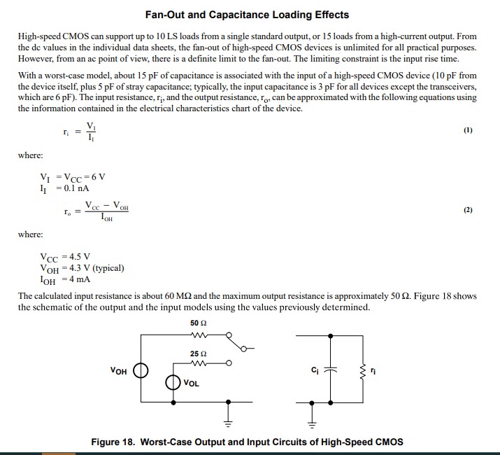
page 17 of TI IIL SN74HC
So the limiting factor is "fanout" not "gate input resistance". High-Speed HC circuits can usually permit fanouts around 1000. Under that, fanout is not a circuit design factor. If logic types other than HC (such as TTL) are driven by an HC gate the maximum fan out limit is often 10. The Conclusion is that the outputs of HC gates require the most design effort. The Pi Pico has another MORE IMPORTANT related design factor. It is the maximum total current that can be drawn from all GPIO pins on the Pi Pico, called IOVDD.
Recently, on 2021BFeb04, jamesh, principal software engineer at Raspberry Pi (Trading) Ltd. posted the following... "IOVDD current <=50mA", to the forum at Source 12 which, I believe, means that the maximum total current that can be drawn from all the GPIO pins on the Pi Pico must be <= 50 mA. Others have stated that the maximum total current that should be drawn by any 1 GPIO pin on the Pi Pico should be 6mA, although up to 12 mA will probably work. Others have said "Draw more than 31 mA from a GPIO pin on the Pi Pico and you might destroy it. Note that a total limit of 50 mA allows almost 2 mA per pin on the Pi Pico. Multiple HC Buffers and an external power supply are indeed wise if the Pi Pico will control many devices.
As of 2021B Feb 23, in Source 12, there is much more information about the GPIO pins on the Pi Pico. It is well worth perusing.
(To enlarge .....Click it)
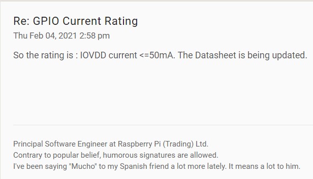
Pi Pico IOVDD
Reading the Serial Number of a Pi Pico
GP00 reads the Serial Number of the PiR2_Pico from the INFO_UF2.txt file in the root of the Pi Pico. Any attempt at writing to the GP00 will initialize the PiR2_Pico and its pin definitions. The contents of the INFO_UF2.TXT file on the Pi Pico will probably resemble that for the nRF52840 shown below:
UF2 Bootloader 0.2.10-4-g79fe6cc-dirty lib/nrfx (v1.1.0-1-g096e770) lib/tinyusb (legacy-755-g55874813) s340 6.1.1
Model: SparkFun Pro nRF52840 Mini
Board-ID: SparkFun-Pro-nRF52840-Mini
Bootloader: s340 6.1.1
Date: Jul 12 2019

Source: https://judepereira.com/blog/tag/sparkfun/
Micro-Python
The Pi Pico is programmable using its MicroPython interpreter on the Pi Pico. MicroPython was originally designed prior to 2018 (see Video Source 04 below).
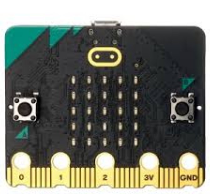
MicroPython was created for programming the simple BBC micro:bit computer (shown below). Documentation describing this version (v1.0.1) of MicroPython can be found in Source 9 below. Some of this information was created by Mike Rowbitt.
Serial Number of an SD card
Posted byu/sparkystuff
5 years ago
Serial number of SD card
I can't seem to find a way to find the serial number of my SD card. I've looked in /dev/disk/by-uuid, but the same uuid is
 used across multiple Pis that I have. I've also used the blkid command, but I can only seem to get the size of the SD
card. Any help would be appreciated.

Edit: I managed to figure out where the "serial number", aka CID, is found. For anyone who's interested, it's located in
/sys/block/mmcblk0/device/cid. The CID contains info on when the card was manufactured, by whom and what its intended
content is. For more information on the SD card standard check this out. I plan on using the CID to encrypt the files on
the SD card so no one can take my card out and simply copy what's on it.

Source: https://www.reddit.com/r/raspberry_pi/comments/3xwqqp/serial_number_of_sd_card/
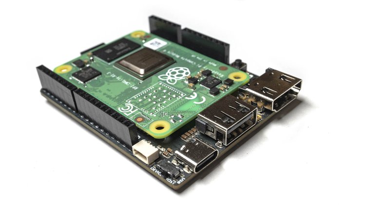
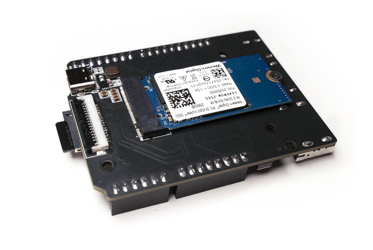
Raspberry Pi RP2040 M.2 card . . Soon
Timon @timonsku
2021CMar 28
wrote, on Twitter (Source 17).
This is a Raspberry_Pi RP2040 M.2 card. It's compliant to M.2 B-Key.
It uses USB at the moment but a future version might integrate a PCI-e PHY.
This is mostly a demonstration that it is easy to make your own M.2 compliant addon cards.
(To enlarge .....Click it)
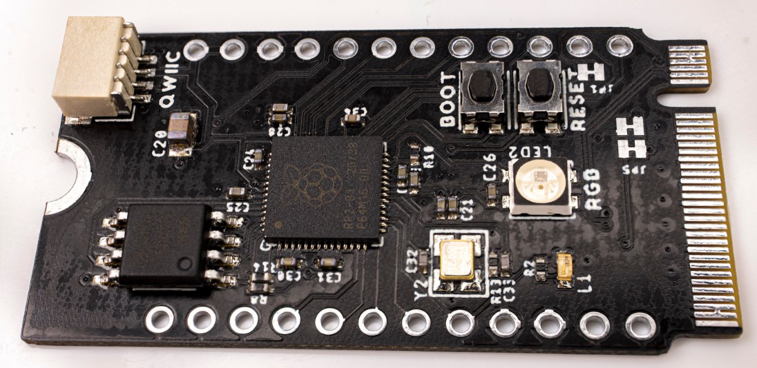
Raspberry Pi RP2040 M.2
Readers should note the Qwiic connector (I2C) in the upper left corner. Although
the M.2 solid state form factor applies to both PCI-e and SATA drives, they do need different controllers. . . . ! See Source 16 for more info.
Compare the features of the RP2040 M.2 with the Piunora board (next) that gets a lot of its power from the Raspberry Pi Compute Module. The RP2040 M.2 offers minimal functionality with the small-footprint Micro-Python language and a (future) interface to a solid-state drive and future memory upgrades.
PIUNORA CARRIER BOARD FOR RASPBERRY PI COMPUTE MODULE 4
The Piunora (Source 18) carrier board for Raspberry Pi CM4 is designed for rapid electronics prototyping in a Linux environment. The official carrier board of the Raspberry Pi CM4 is large as it covers all features required. Whereas, the Piunora carrier board comes with similar functionalities but with a smaller form factor similar to Arduino Uno or Adafruit Metro. It also features GPIO, HDMI, USB, and power connections from the Broadcom BCM2711 SoC as the PCle interface.Timon`s Piunora carrier board has SoM compatibility for specific functionalities with a quad-core Cortex-A72 processor working at a frequency of 1.5 GHz. It offers RAM from 1GB to 8GB with an optional 4GB to 32GB eMMC flash memory. The carrier board comes with an optional wireless module with 802.11b/g/n/ac WiFi 5 and Bluetooth 5.0 . It has a MicroSD card socket for the operating system while working on Raspberry Pi CM4Lite as an SoM. The HDMI 2.0 port comes with a 4Kp60 feature for real-time video output. The camera interfaces with a MIPI connector to a USB 2.0 port or USB-C port with support for data and power using a host switch.
Suppliers
A US supplier of the above components is Sparkfun (Source 4 below). Similar Canadian suppliers are BC-Robotics (Source 5 below) and Mouser Electronics (Source 6 below).
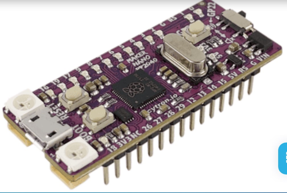
Maker Nano RP2040 by Cytron
This board is a much smaller version of the Maker Pi Pico board. It was probably designed as a replacement for the Maker Nano Arduino board (although it may not be pin-to-pin compatible with it.
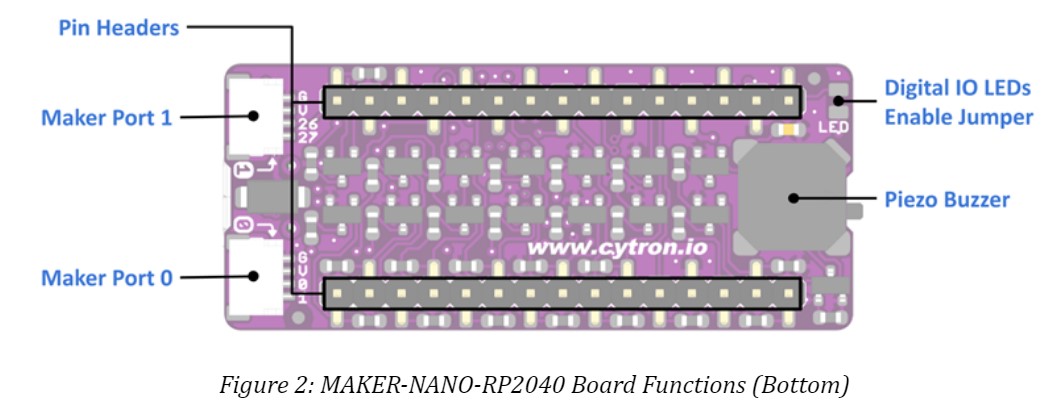
Because its size is much smaller than the Maker Pi Pico board, many components have not been included. This board, being smaller, has only 2 Qwiix / Grove connectors; there are no connectors for
a microSDcard nor an audio jack. Furthermore, all 40 pins of the RP2040 are not accessible.
The author has not yet tried to install and run the MMBasic software (see Article 166) onto this board. But it is expected to function correctly. Readers are cautioned to only drive SN74HC components from the pins of the Maker Nano RP2040. It is important to properly buffer any power-hungry devices. A suitable buffer would be an SN74AHC541N buffer by ti available from Mouser for less than US$1.00 each. Furthermore, readers should ensure that sufficient current is available from elsewhere if the Maker Nano RP2040 cannot provide it.
(To enlarge .....Click it)
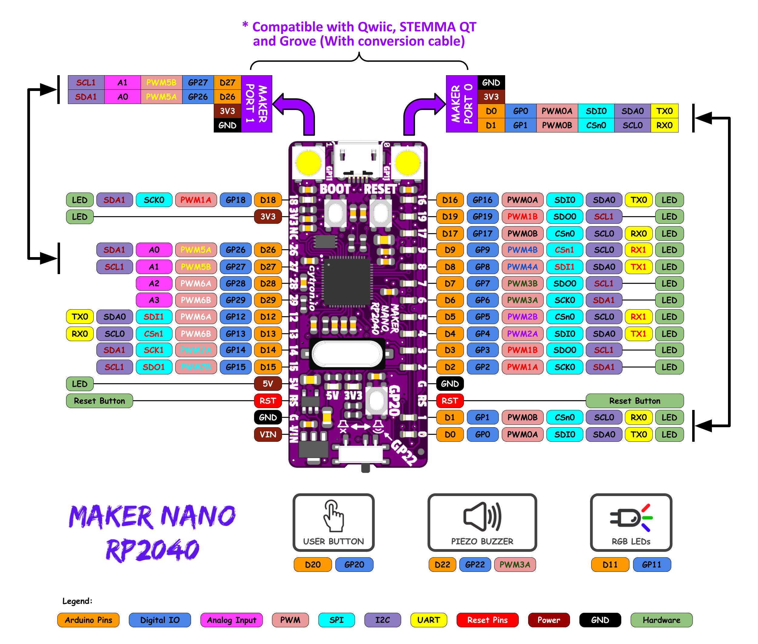
Cytron Maker Nano RP2040 Pinout Diagram
In Feb 2, 2022, Cytron announced a very tiny board (shown above) designed around the Raspberry 2040 IC. It is similar to the Maker Pi Pico board, costs US$8.46, but is
much smaller than the Maker Pi Pico board. It is more powerful than the Arduino Nano but has the same form factor. A schematic of the board is not yet available as of Feb 2022. The Maker Nano RP2040 has the following features:
 1 micro USB connector (for communications with the Host PC and to supply power to the Maker Nano RP2040. )
14 GPIO LEDs (D0-D9 plus D16-D19)
 2 RGB (WS2812 Neopixel) LEDs (D11)
 1 Piezo Buzzer with a Mute switch (D22)
 1 User Button (GP20)
 2 Maker I2C Ports (Qwiic ports, Grove compatible using 2 cables included)
       Port 0 is for asynchronous serial UART communication  (Tx & Rx) (D0 & D1)
       Port 1 is for A0 and A1 which are ADC (Analog to Digital Convertors (D26 & D27)
      Each Maker Port has a JST-SH 4 ways connector and uses I2C communication
 2 Additional ADC (A2 & A3) are available on pins D28 and D29)
 2 RP2040 switches (BOOT and RESET)
 1 16,000 kHz (16MHz) crystal for the RP2040 clock
 1 RP2040 Raspberry Pico IC
30 male pins (to plug into a breadboard)
    Flash Memory 2MB
    SRAM 264KB
    Vin Voltage: 7 to 30V
    Internal supply voltages: 3v3 & 5v0

 NB The USB Cable to host is NOT included.
Software that it supports includes IDE, CircuitPython and MicroPython (Thonny).
This is the End of this Article.
Video Sources
Video Source V151:01: RP2040 Deep Dive  (2:28 hr) w/Scott of Adafruit Industries
Video Source V151:02: Pi Pico Showcase (6:36 min) by Sparkfun as of 2021AJan21
Video Source V151:03: Pi Pico Not Like the Others (7:07 min) by etaprime as of 2021AJan22
Video Source V151:04: Writing .... MicroPython (31:41 min) by Damien George as of 2018HAug 24
Video Source V151:05: How to read the temperature sensor on the Raspberry Pi Pico (13:07 min) by learnelectronics as of 2021A Jan 29
Web Sources
Web Source S151:01: Pi-400  by the Raspberry Foundation
Web Source S151:02: Compute Module 4 IO board  by the Raspberry Foundation
Web Source S151:03: Pi Pico by the Raspberry Foundation on 2021 A Jan 23
Web Source S151:04: Sparkfun as of 2021AJan24
Web Source S151:05: BC-Robotics as of 2021AJan24
Web Source S151:06: Mouser Electronics Canada reselling Seeed products as of 2021AJan24
Web Source S151:07: RPI-400 Product Brief (pp 1-8) by Raspberry as of 2020KNov
Web Source S151:08: RP2040 Datasheet (pp 1-636) by Raspberry Pi as of 2021AJan24
Web Source S151:09: MicroPython v1.0.1 for the BBC micro:bit computer V2 by multiple authors (c) 2015-2016
Web Source S151:10: Raspberry Pi Pico Guide (pp 1-139) by Raspberry as of 2021AJan 21
Web Source S151:11: Example in "C" code to read BOOTSEL button  by kilograham on GitHub as of 2021AJan 20
Web Source S151:12: Pi Pico GPIO source/sink currents by GregAC on 2021 Jan 30
Web Source S151:13: .... datasheet sink source current.... by paul296 on 2017 Jan 26
Web Source S151:14: HCMOS Design Considerations by ti on 2002I Sep
Web Source S151:15: Pi Pico GPIO source/sink currents CD74HD132 4x 2 input NAND by ti on 2021B Feb 22
Web Source S151:16: M.2 Keys and Sockets
by ATP on 2018J Oct 25
Web Source S151:17: Pi RP2040 with M.2 form factor by ATP on 2018J Oct 25 on Twitter
Web Source S151:18: Piunora Carrier Board for Pi Compute Module 4
by Electronics Lab on 2021A Jan 21 on Twitter
Web Source S151:19: Maker Nano RP2040
by Cytron on 2022B Feb 12
Web Source S151:20: Maker Nano Data Sheet (6 pages) by Cytron on 2021 L Dec 21
Web Source S151:21: Pi: New Raspberry Pi Products eg Pi-400 c2021 (151.html) by D@CC on 2021A Jan 24
Web Source S151:22: Pi: Useful Raspberry Pi Device Family Terminal Commands (170.html) by D@CC on 2022 B Feb 04
Created : 2021A Jan 24
Updated: 2023J Oct 09
/151.html