Pi: Pix voltMeter_pico (180.html)
Keywords
Raspberry Pi Pico "voltMeter_pico" vMeterIXAA_pico.py RAPasc "complex number" ADC0 ixProbe Tiny2040
pi/pico_4f31_on_Fla53 vMeterIXAA_pico_py.txt 10K0 100K0 3v3 voltmeter volt-meter readings
"Raspi pico" RP2040 "attenuation factor 9" Device:105 :105
"pin 35" ADC_VREF
"pin 33" GND AGND
"pin 31" GP26 ADC0
/KeywordsEnd
(To enlarge .....Click it)

IX or DC (IX by DC) or "|><"
This software is a part of the IX family of software.
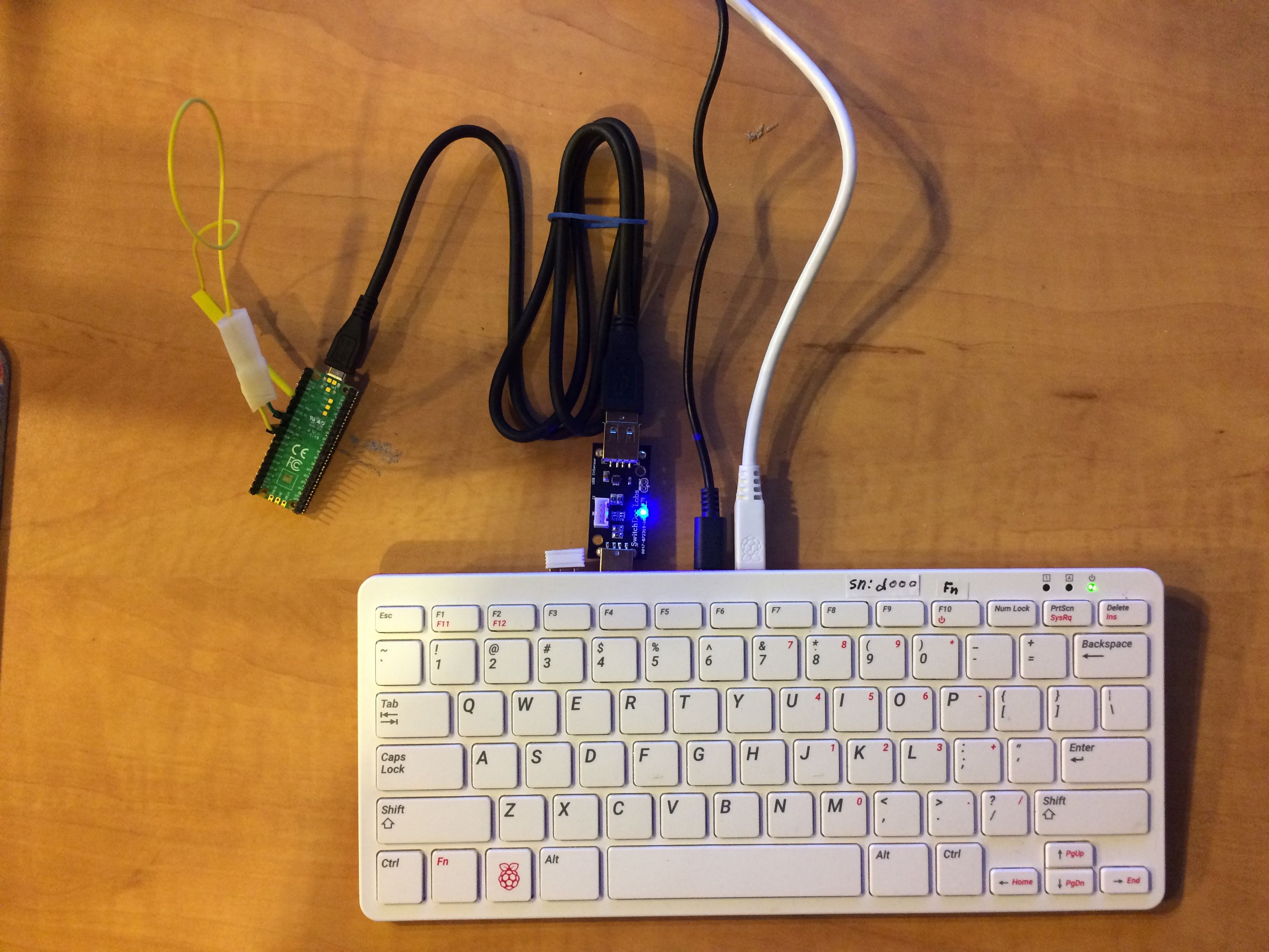
The ixProbe (above) (Device:105) is seen measuring the ADC_VREF which is 3V3.
Introduction
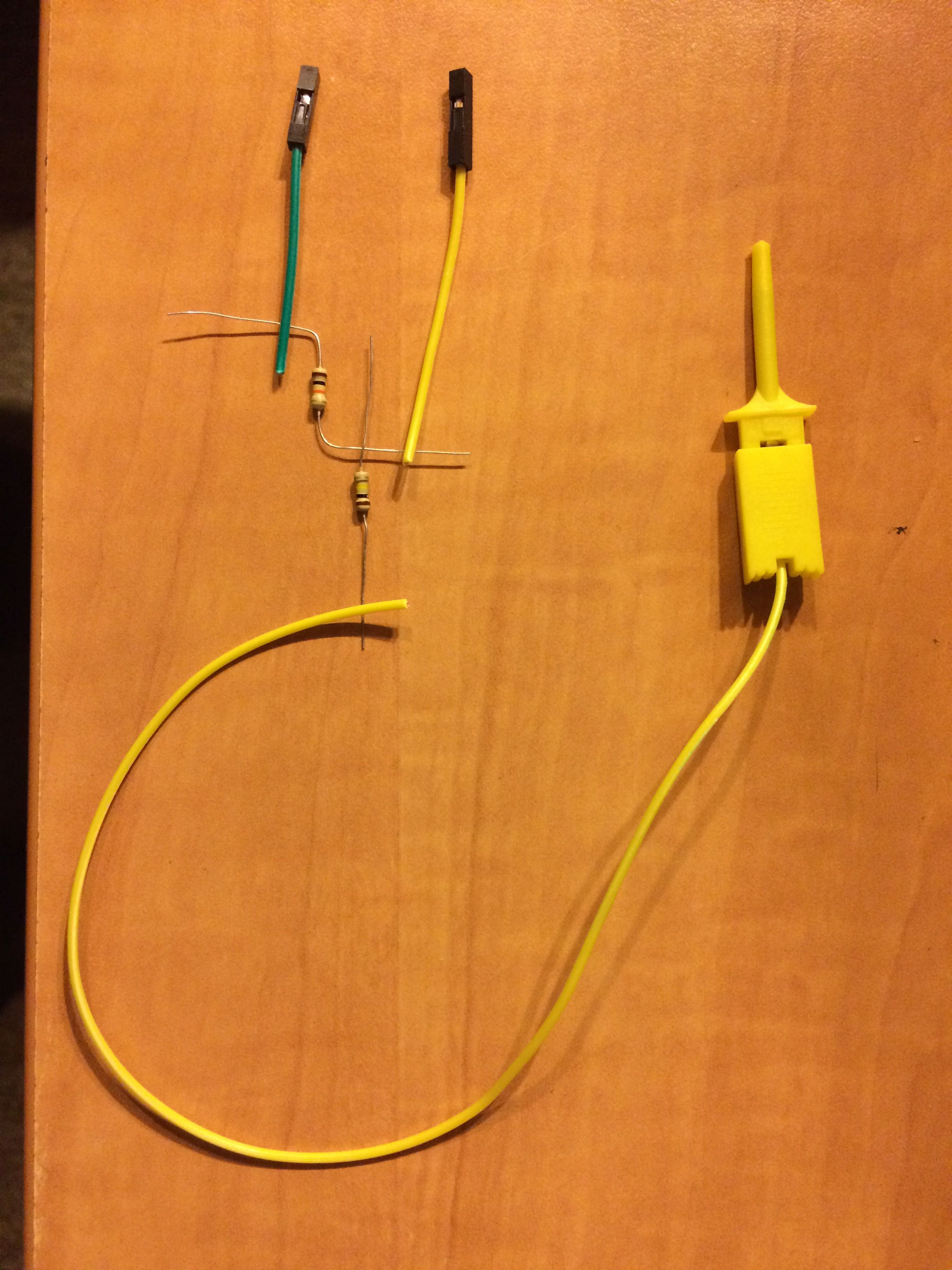
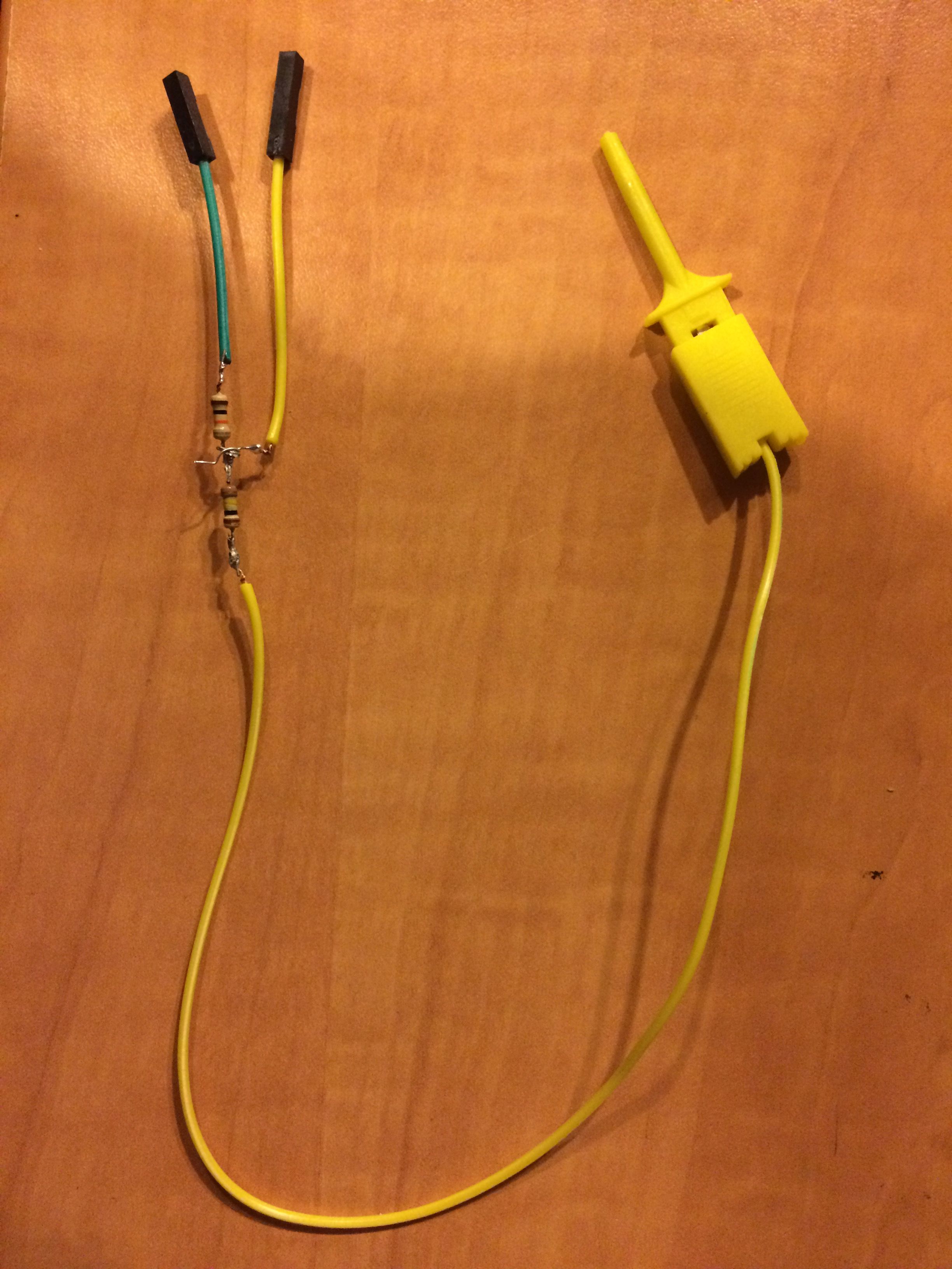
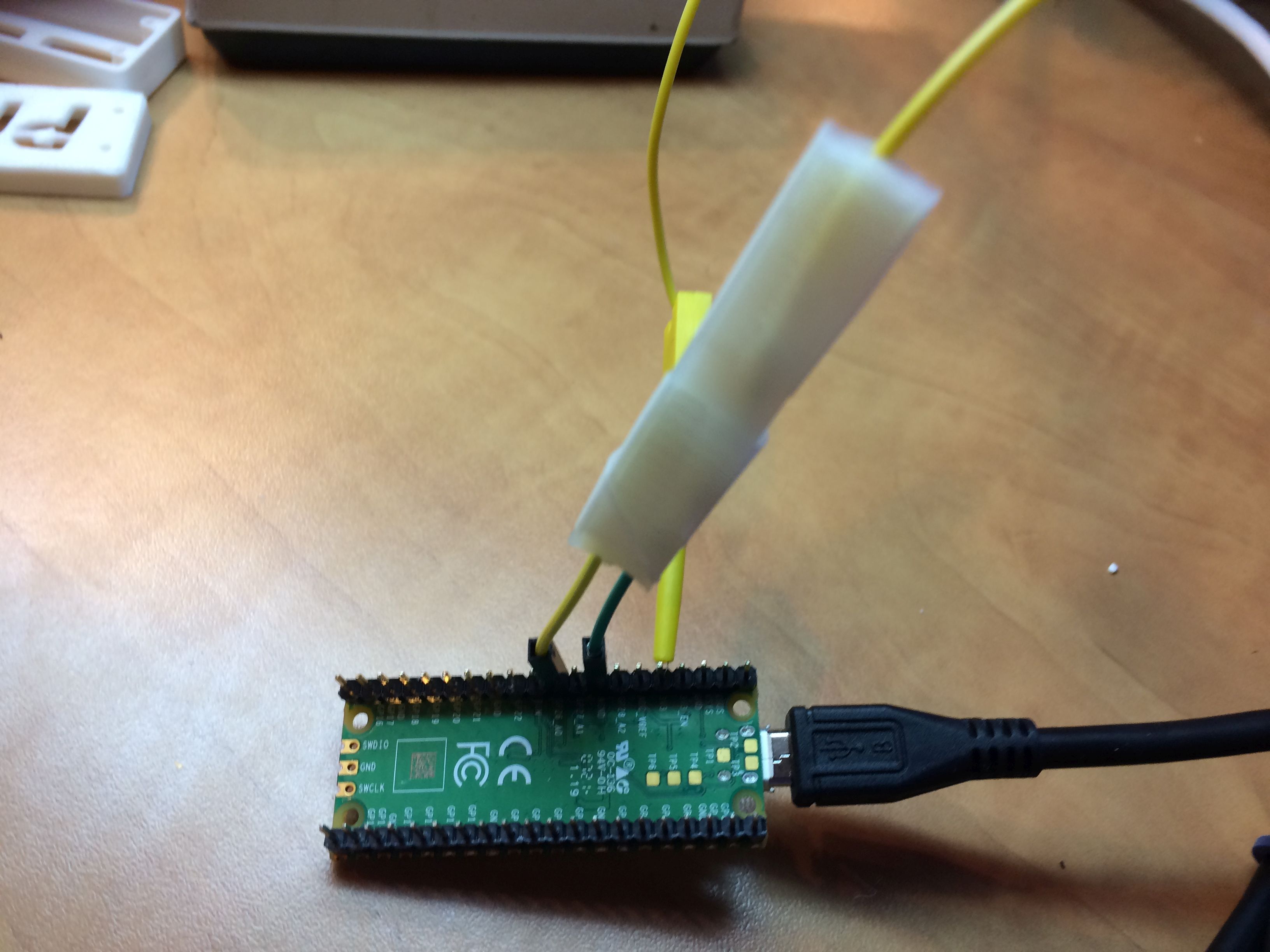
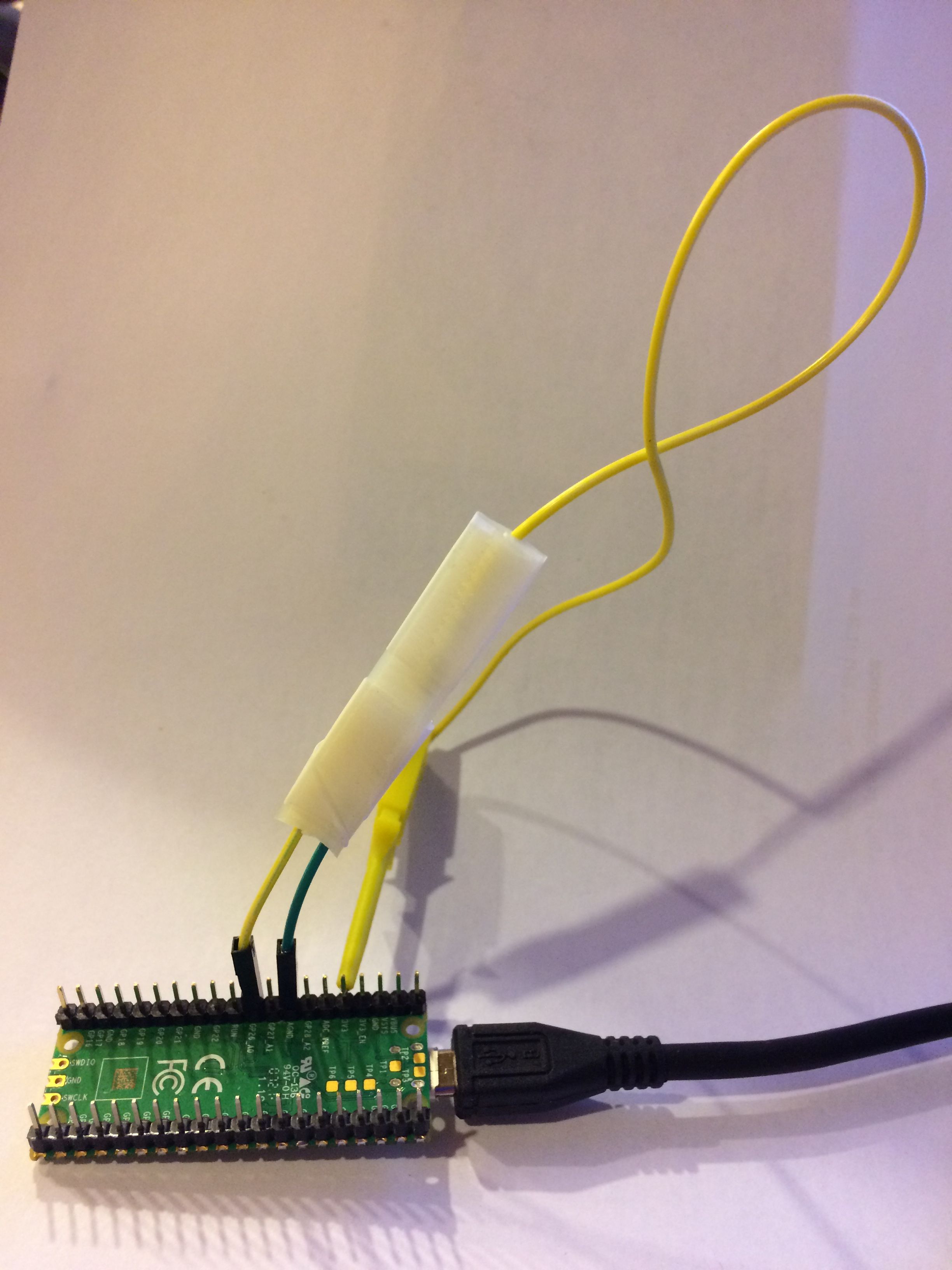
This voltmeter (Device:105) is a probe read by a pico controlled by a Raspberry Pi. The top left photo shows the components in the probe before soldering. The top right photo is the soldered probe. Below that on the left is a close-up of the finished probe attached to the pico. To its right is the probe and the wire connecting it to the pico. The lower left photo is the probe and pico with the INA219 connecting them to the Raspberry Pi400.
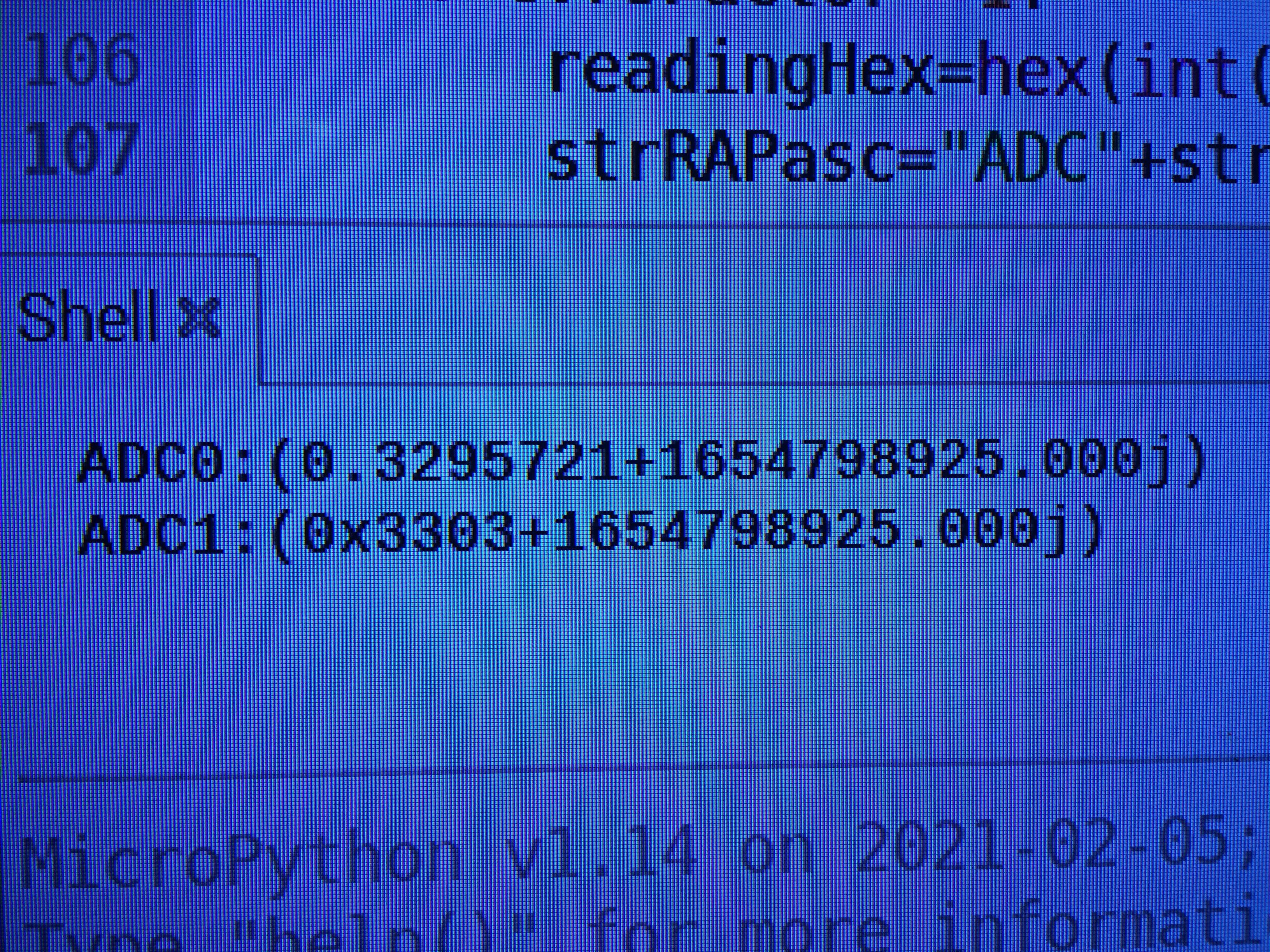
The lower right photo (on the upper line) is one voltage reading (of ADC0) photographed on the monitor connected to the Pi400 that is running the voltMeter program.
The voltMeter Program
Web Source 01 contains the first version of the voltmeter program named vMeterIXAA_pico.py. This program takes a series of readings and delivers them to the Pi400 in one of three formats:
a set of a number of voltage readings that are:
 - voltage values displayed in a list.
 - the same voltage values displayed one after another in RAPasc format (Source 01 and Article 165 which is Source 06)
         (each on a row along with the time stamp when they were measured).
 - a continuous display of the instantaneous voltage values
         (one per row in real time with time stamps, using approximate milliseconds.)
This program, vMeterIXAA_pico.py, (in Web Source 01) is my first attempt to design and develop a software tool that will deliver the time-stamped RAPasc voltage readings to the Raspberry Pi400 computer, each reading being a complex number.
Complex Numbers
Complex numbers are comprised of a real and an imaginary part. The imaginary part is followed by the letter "j". Python on a Raspberry Pi can store and process complex numbers. But the Raspberry Pi Pico cannot. However, the Pico can print complex numbers in the ascii format even though it cannot do arithmetic on the complex numbers. Therefore, the Pico simply sends the readings as complex numbers to the Raspberry Pi computer. The number 0.3295721 is the voltage that was measured. (The program now multiplies it by 9 to display the actual voltage that the probe measured.) The imaginary part is the number 1654798925.000 that precedes the "j" in the ADC0 number photographed on the screen. The imaginary part is the unix time that represents the date and time when the reading was recorded. By using a complex number, the reading and its time-stamp are married together in a single complex number.
The ixProbe
The actual ixProbe is 1 lone yellow wire attached to a tiny yellow (probe) clamp. The "return" wire is connected to the pico by a common ground between the pico and the circuit under test. Because the pico would be damaged if a voltage higher than 3v3 were measured, the ixProbe attenuates (lowers) the voltage by a factor of 9 before it is measured. By doing this, any voltage up to 29v7 can be safely read. The circuit and the vMeter program convert the attenuated value of the voltage (that was read) back to its proper value before being reported to the user. The ixProbe is attenuated by a 10K0 and a 100K0 resistor as shown below:
   AGND  female pin -----yellow wire -------------------------|
                                                              |
                                         |-----10K resistor---|---- 100K resistor ---- yellow probe tip clamp  ADC_VREF
   ADC0                                  |
    /    female pin -----green wire------|
   GP26
The assignment of the Pico pins can be seen below:
(To enlarge .....Click it)

Raspberry-Pi-Pico-techatronic (top view)
pin 35       ADC_VREF
pin 33  GND  AGND
pin 31  GP26 ADC0
RAPasc Voltage Reading Format
As can be seen in the lower right photo above the introduction, the ADC0 reading appears on the first line. The reading is written as a complex number. The real part of the complex number is the actual voltage reading (attenuated by 9 in the photo). The imaginary part of the reading is the actual Unix time when the reading was taken. The lower ADC1 reading can be ignored as it has been removed from the current voltmeter program. The name RAPasc refers to a Reading of an ADC pin (with Periods) as an ascii string with a "j" after the imaginary portion.. "With Periods" indicates that the number which is the voltage reading includes a period (decimal point) as does the Unix time-stamp number. An example of a RAPasc number can be seen in the bottom right photo that appears earlier in this article.
INA219
The INA219 is a board from Spark-Fun that permits measurement of the voltage, current, Rx and Tx lines that connect a male USB connector to a female USB connector. The INA219 has a Grove connector that permits the voltage and current to be read by a 2nd Raspberry Pi computer that connects to the Grove connector. The INA219 would normally be inserted between a 2nd Raspberry Pi computer and a Pico microcomputer. The Pi is the Master node; it is controlling a Slave node such as a 2nd Pico. The link between the Master and Slave in this case is a USB cable or equivalent INA219.
Tiny2040
The Tiny 2040 (in Video Source 01 below) is simply a smaller variant of the Raspberry Pi Pico. It can measure 4 voltages on 4 different pins whereas the Pico can measure voltages on only 3 pins. To measure 4 voltages, 4 ixProbes would be needed.
Reading ADC very fast
See Source 02 to see how to read a pico ADC very quickly and how to convert it using FFT. Source 03 uses Micro-Python to read samples very quickly. Source 04 is the source file (zipped) for Source 03. Source 05 is the main program form Source 04 that reads the ADC and displays the results. You will need to rename Source 05 to change its extension to ".py".
Sources
Video Sources
Video Source V180:01:
First Look at the Tiny2040 (3:14 min)  by Learn Embedded Systems c2021DApr
Web Sources
Web Source S180:01:
vMeterIXAA_pico_py.txt (in Thonny Python)  by D@CC on 2022FJun11
Web Source S180:02:
ADC Sampling and FFT on Raspberry Pi Pico (at 500KHz - fast) [C/C++ code]  by Alex Wulff on 2021AJan31
Web Source S180:03:
Pi Pico ADC input using DMA and MicroPython (at 500K Samples/s) [Micro Python code]
by Jeremy P Bentham on 2021JOct26
Web Source S180:04:
pico-main.zip from GitHub for Source 03 above (zipped file) [Micro Python code]  by Jeremy P Bentham on 2021JOct26
Web Source S180:05:
rp_adc_test_py.txt in pico-main.zip from GitHub for Source 03 above (py.txt file) [Micro Python code]
by Jeremy P Bentham on 2021JOct26
Web Source S180:06:
Pi: MAK Pi ADC and RUPasc by ICH180RR (165.html)
by D@CC on 2021FJun22
/SourcesEnd
WebMaster: Ye Old King Cole
There is a way to "google" any of the part-numbers, words and phrases in all of the author's articles. This "google" search limits itself ONLY to his articles. Just go to the top of "Articles by Old King Cole" ( www.ephotocaption.com ) and look for the "search" input box named "freefind".
Date Written: 2022 F Jun 11
Last Updated: 2024 D Apr 04
All rights reserved 2024 by © ICH180RR
Font: Courier New 10
/180.html