PiWithPico
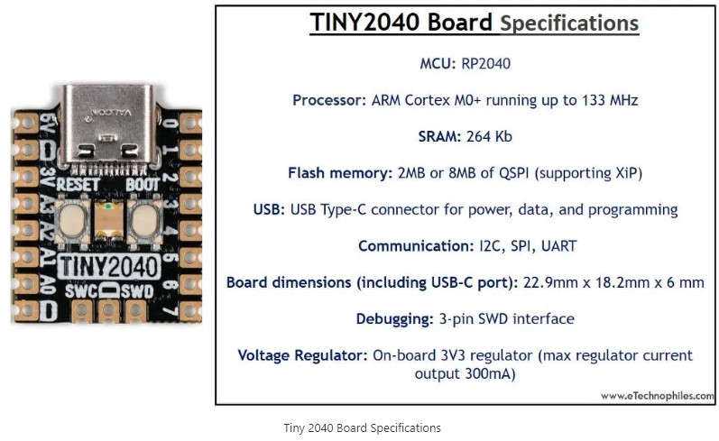
TINY2040 Top View

|
(To enlarge .....Click it)
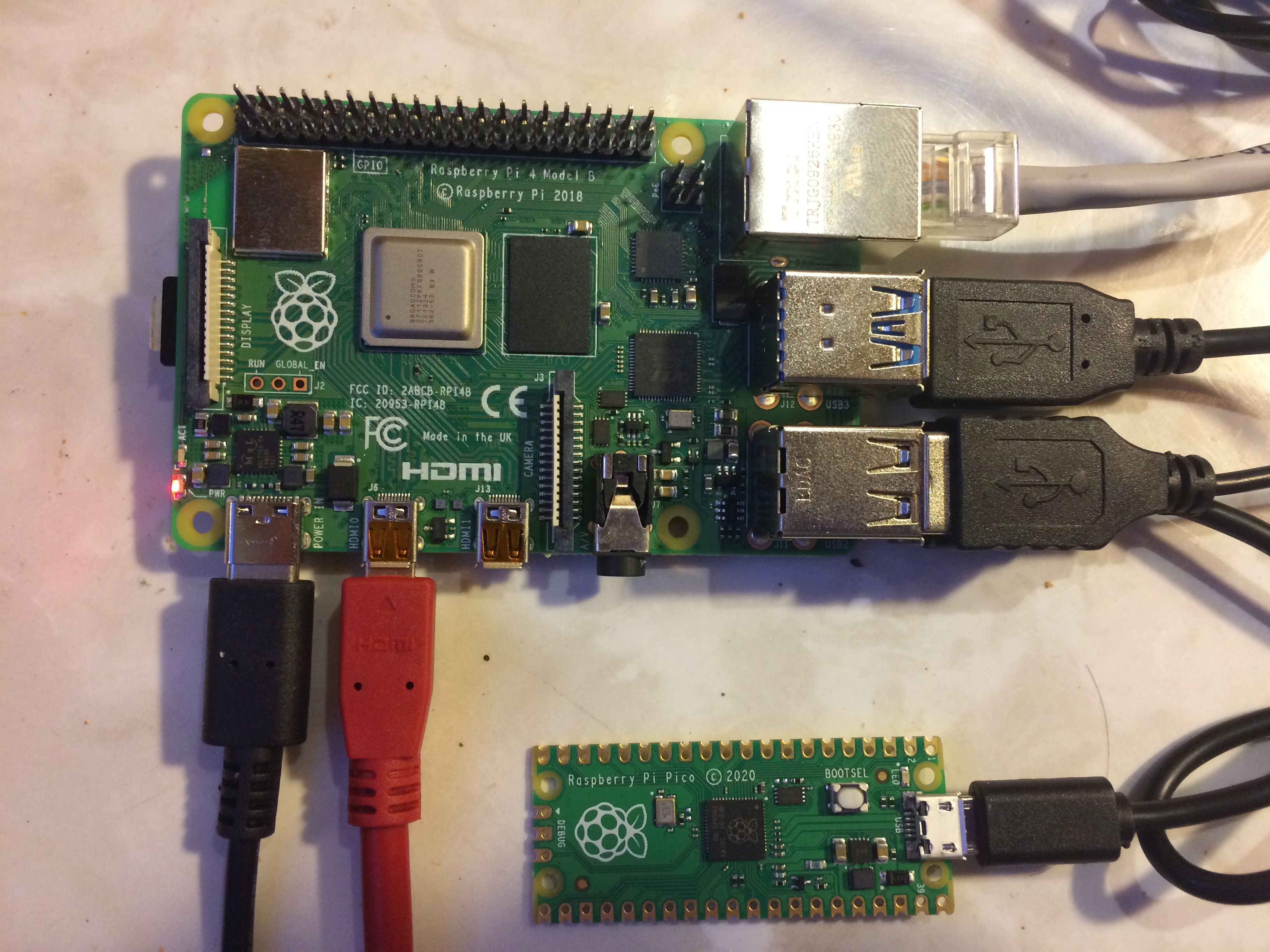
PiWithPico |
(To enlarge .....Click it)
TINY2040 Top View |
                 COMMAND   TYPE        ID          F_CONVERT   VALUE      PREVIOUS

 1 Command Sent: PixRead    ,ADC        ,1          ,Unary
   Reply       : value      ,ADC        ,1          ,Unary      ,4032

 2 Command Sent: PixWrite   ,GP         ,5          ,Unary      ,1
   Reply       : written    ,GP         ,5          ,Unary      ,1

 3 Command Sent: PixRead    ,ADC        ,1          ,VoltsMax3v3
   Reply       : value      ,ADC        ,1          ,VoltsMax3v3,3.29

 4 Command Sent: PixWrite   ,GP         ,99         ,Unary      ,1
   Reply       : error      ,GP         ,99         ,Unary      ,1

 5 Command Sent: PixRead    ,MODEL      ,1          ,Unary
   Reply       : value      ,MODEL      ,1          ,Unary      ,TINY2040

 6 Command Sent: PixWrite   ,MODEL      ,1          ,Unary      ,TINY2040
   Reply       : written    ,MODEL      ,1          ,Unary      ,TINY2040   ,Unknown

 7 Command Sent: PixRead    ,SN         ,1          ,Unary
   Reply       : value      ,SN         ,1          ,Unary      ,None

 8 Command Sent: BPS        ,UART       ,0          ,Unary      ,9600
   Reply       : value      ,UART       ,0          ,Unary      ,9600       ,300

 9 Command Sent: HELP       ,PIX        ,0          ,Unary
   Reply       : value      ,PIX        ,0          ,Unary      ,e.g. BPS UART 0 Unary 9600

10 Command Sent: PIX        ,HELP       ,0          ,Unary
   Reply       : value      ,HELP       ,0          ,Unary      ,e.g. BPS UART 0 Unary 9600

11 Command Sent: PKTIX      ,DOCS       ,0          ,Unary
   Reply       : value      ,DOCS       ,0          ,Unary      ,ePhotoCaption.com/a/177/177.html

12 Command Sent: DOCS       ,PKTIX      ,0          ,Unary
   Reply       : value      ,PKTIX      ,0          ,Unary      ,ePhotoCaption.com/a/177/177.html

13 Command Sent: LIST       ,COMMANDS   ,0          ,Unary
   Reply       : value      ,COMMANDS   ,0          ,Unary      ,PixRead PizWrite BPS PIX PKTIX LIST READFILE RUN etc

14 Command Sent: READFILE   ,EXAMPLES   ,0          ,Unary
   Reply       : value      ,EXAMPLES   ,0          ,Unary      ,list of examples (14) follow

15 Command Sent: RUN        ,hello      ,0          ,Unary
   Reply       : value      ,hello      ,0          ,Unary      ,Hello World

16 Command Sent: HELLO      ,hello      ,0          ,Unary
   Reply       : value      ,hello      ,0          ,Unary      ,Hello World

17 Command Sent: RUN        ,environ    ,0          ,Unary
   Reply       : value      ,environ    ,0          ,Unary      ,model: Pico RP2040

18 Command Sent: SET        ,EOL        ,0          ,Unary      ,IOS
   Reply       : value      ,EOL        ,0          ,Unary      ,IOS        ,LINUX

19 Command Sent: EOL        ,EOL        ,0          ,Unary      ,T
   Reply       : value      ,EOL        ,0          ,Unary      ,IOS        ,LINUX
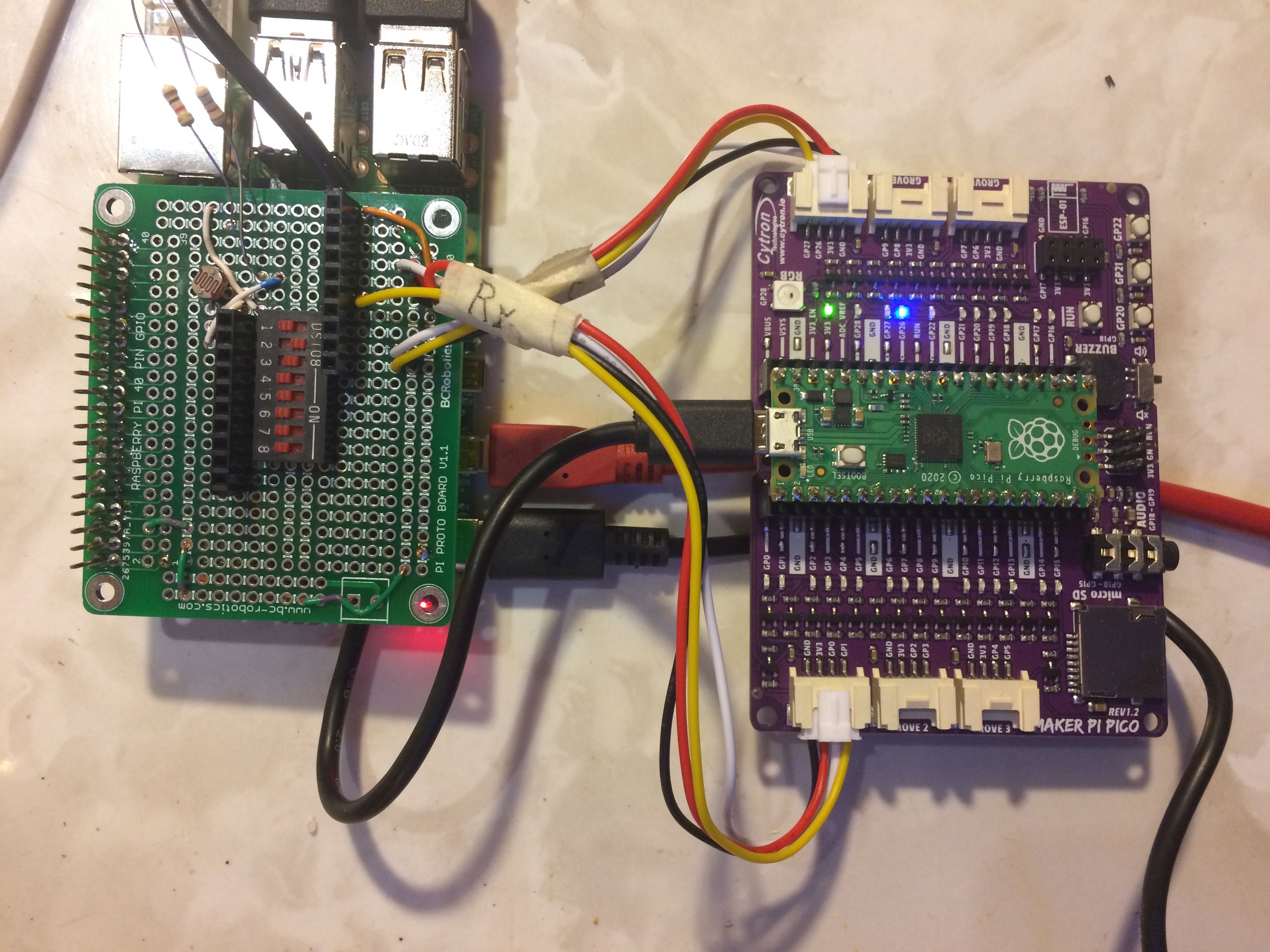
This protocol is part of the routine named Pix_pico.py which runs in the Pico. The protocol in the Raspberry Pi is part of the routine named Pix_pi.py which runs in the Raspberry Pi. The Pico can be controlled interactively in real time by simply sending the above command to the Pico via the
serial port of the Pico. The reply will be sent back to the serial port via the USB connector on the Pico. Note that the command and the reply are composed of comma-delimited ascii text fields (each field is 11 characters wide) followed by a LF. [Note that 11 characters can store the highest signed 4 byte integer which is -2147483648]. Early versions of the Pix_pico.py software will use this format. Eventually, all space characters in the command and the reply can and will be ignored. This ultra-simple ascii communication protocol permits any modern computer to control the Pico. These routines will be tested on the Raspberry Pi using the Thonny python software language. One of the secondary routines to be developed will be the Command "PixInstall" which will download to the Pico various modules of the current version of the Pix software from the Raspberry Pi.Tri-Color LED Control in the Pix ID field "pin" Pix Name Color GP18 R-LED Red GP19 G-LED Green GP20 B-LED BlueThe above table shows the names of the internal logical pins that must be referenced to display each color. There are no equivalent external pins to these 3 pins. Unfortunately, the TINY2040 pins have been defined with active-low logic which is opposite to the logic of the green LED on the Pico. If a TINY2040 is the model specified, the Pix software will automatically use the F_CONVERT function named "Invert", so that the G-LED command for a TINY2040 will have the same effect as the G-LED command for a Pico. Note that for the Pix software, the "Green" pin can be referenced using any of the three names: GP19, G-LED or LED. There is a Tri-Color LED on the Maker Pi Pico board, but it is controlled differently. The Pix software will (in a future version) turn on the correct color if the Pix Name is specified for a model of "MakerPiPico". Various intensities of each color can be produced. But such intensity control will not be available in early versions of the Pix software.
                 COMMAND   TYPE        ID          F_CONVERT   VALUE

   Command Sent: PixWrite ,LED        ,G-LED      ,Unary      ,T
   Reply       : written  ,LED        ,G-LED      ,Unary      ,1
It might seem strange that the prior state of the LED is reported in the reply to the PixWrite LED command, but, in fact the value of the LED prior to it being "written" is what is indicated in the reply. It would provide no new information if the "new" value of the LED were returned. Because the previous value of the LED is available, it is returned in the reply.
                 COMMAND   TYPE        ID          F_CONVERT   VALUE

   Command Sent: PixRead  ,ADC        ,4          ,TempC
   Reply       : value    ,ADC        ,4          ,TempC      ,16.4
There are 4 ADC devices in the Pico 2040 but only 3 of them are externally usable, referenced as ADC0, ADC1 and ADC2. Nevertheless, the internal chip temperature sensor is referenced as ADC4. ADC3 is not defined for the Pico, perhaps because there is no physical ADC3 pin. The TINY2040 has 4 external physical pins: ADC0, ADC1, ADC2 and ADC3. The Pico can read the ADC_REF from physical pin 35. The TINY2040 does not have an equivalent pin to the ADC_REF.
sudo apt-get install minicom
Pico Software on pico 4f31
as of 2022 E May 30
by D@CC
on Fla53S032G

Routine             Function       Description
******************  *************  ***************************************
1Char.py            bChar()        Converts b'w' to "w"
adcValue.py                        Prints adc value & voltage on pico ADC0
BoardId.py                         X reads Board ID
deviceReset_pico.py                Blinks then Resets all pins as Inputs
f3.py               f3()           format any number for printing
fadeLed_pico.py                    Fades the pico green LED using PWM
maker-pi-pico-rgb-led_pico.py      maker board demo program
intRed_pico.py                     drives Green LED and button 21
mid.py                             X converts any number to complex format
mod5.py                            X first MicroPython program
mod8.py             import mod6    first MicroPython program
mpy_uart_pico.py uart.read         read/write using pico uart
parseComplex.py                    converts a complex number
picoButton_pico.py                 reads pico Button 22 on Maker board
printPicoUniqueId.py               Prints unique ID (char) of pico
printTImTemp_pico.py               Prints Time and Temperature F of pico
serTxC_pico.py                     X packet transmitter by D@CC
serTxRx_Fast_pico.py               X packet tx / rx by D@CC
signalGenerator_pico.py            hacked signal generator
signalGenerator_w_PotOn1_pico.py   worked with MakPiADC board
squareWave_pico.py                 drives Maker pico buzzer
test_TxH_pico.py                   packet transmitter (reads ADC) by D@CC
test_VSYS_pico.py                  Reads Vbus and Vsys
testButton_pico.py buttonAction()  reads button within T (secs)
testLeds_pico.py                   drives Maker pi (not pico) board
testPlot.py          plot()        tests plotting of a vector
testTxF_pico.py                    tested OK on pico
textpack_py.py                     source module transmitter for pi
tickLed_pi.py                      blinks the pi led

                     saveed in Pi/pico_4f31_on_Fla53
/Pico_Software.txt
  msgOut = """
    #B +
    "BPS" +
    oxC +
    """

  Note that the """ should be ignored in the above definition of msgOut.
pktix/pix ERROR: No space prefix. Use 9600 N81.
Prefix each command with the space character (ePhotoCaption.com/a/177/177.html).
   e.g. space,BPS,Enter   or     space,HELP,Enter *********555555555.
Note that a 2 second delay will be inserted between the "Help,Enter" and the first "*"
     I
    C
  msgOut = """
    S +
    D +
    E +
    P +
    C"""


    # where (in the basic pktix) each field will contain
    # I is the letter "A" meaning "1 to 16 packets of exactly 16 bytes each (pktSize)"
    # S is SOM
    # D is Data text to be sent (will not include any unescaped EOM or "/" characters
    #     and will be followed by one EOM)
    # E is EOM
    # P is the padding characters (enough EOMs to fill the last packet)
    # V is t5c   (5 character time delay: "roman numberal V")
    # X is t10c  (ten character time delay: "roman numeral X")
    # C is t100c  (100 character time delay: "roman numeral C")

    # R is the address of the pico Card (at least the rightmost 4 characters of the SN of the Pico card)
    #        (the previous value of "A" has been deprecated, "R" can be the Rightmost 4 characters
    #         of the Pico card or the full Serial Number of the Pico card.)
    # L is the number of data characters in all packets in the whole message (not used in basic pktix)
    # N is the packet number (not used in basic pktix)
    # F is the hash code function name (not used in basic pktix)
    # H is the hash code (not used in basic pktix)
    # B is a space (0x20) (must be the first character of each message when "I"=" "

    # Most basic messages will have msgOut = "IC" "SDEPX"
    # An escaped EOM in a basic pktix message data is a "/E", each "/" must be escaped as "//", each
    #     EOS must be escaped as "/S" all 3 being included in the character count in the message,
    # A message field requiring more than one packet will have a packetized format of
    #    SDEPX which is "SDV" "DV" "DV" "DEPX"

    # Between messages, each transmitter will send "0" (0x30) every minute indicating that it's alive but
    #  has no message to send.
    # Before sending each message the transmitter will send a single character which is usually an "A" (0x41) indicating
    #  that the following message will be at most 16 packets of 16 bytes each.  In the future when the packet
    #  size can be 256 characters, the transmitter will precede each message with a single "B" (0x42)
    #  indicating that each packet will contain 256 characters.  This will allow future message lengths
    #  at least as big as 256 x 256 = 65536 characters.  This is a total message length of 65536 characters.
    #  Later, "C" (0x43) will indicate a packet size of 65536 characters.

    #  Future advanced versions of pktix will have a 5-field msgOut = "SEV" "SAEV" "S0xLEV" "SDEPX" "SF:HEPX"
    #   with each data field having the format :
    #        SDEPX which is SNDV NDV . . . . NDV etc NDEPX
    # Note that each packet is preceded by its packet number (N) in advanced pktix.
    # The optional advanced pktix Null message of SEC SEC S0x0EC SEC S:EC re-establishes asynchronous synchronization
    #  and can always be ignored.
    #
    # In the pktix Protocol, the following conventions apply:

    #    In basic pktix,   if "I" = " ", no packets nor packet numbers nor SOM nor EOM are used
    #                          if "I" = "A" , packets are used but no packet numbers are used.
    #                          Issue!!! U should not be used (i.e. U means a Null byte string)
    #    In advanced pktix, when I = "B" or "C"
    #                            N represents the use of 2-byte (base 256) packet number.
    #                       when I = "A", packets are used but no packet numbers are used.
    #                                    N should not be used (i.e. N means a Null byte string)
    #                       when I = " ", no packets nor packet numbers nor SOM nor EOM are used
    #  L is the exact 4-byte message character "Count" not including the initial SOM nor the final EOM character(s)
    #                       ISSUE!!! when is "L" used??????
    #  V is t5c  (5 character time delay: "roman numeral V")

    # In addition to the above:
    #  *  is a full packet of "*" (0xAA or 0x55) characters (optional for synchronization)
    #     with the format:
    #     S**********************Ev

    # When a pktix receiver starts up (and between messages) it should begin by expecting packets of single
    # characters.  It will read a single 8-bit character expecting it to be a "0" meaning an idle transmitter.
    # If it is not a "0", it will keep reading single characters until it reads a "0".
    # After it reads a "0", it will read another single 8-bit character expecting it to be an "A".  If it is not an
    # "A", the character will be discarded, but the receiver will presume that it is reading a character
    # stream that is mid-message.  It will read single 8-bit characters searching for a "]" which will indicate
    # that this is the last packet of the message. It will keep reading and discarding all the "]" that it sees.
    # After the last "]" or after a quite time, the next 8-bit character should be a "0".  The receiver should
    # keep reading and discarding the "0"
    # characters.  When an "A" is finally received (while reading single 8-bit characters) after a "0", the receiver
    # will presume that subsequent packets will be packets of 16 characters.  The receiver will now supposedly be fully
    # "synchronized" with the transmitter".  It is important that these single character message groups precede each packet stream.
    # This is because the receiver must know the expected packet size so that the "read characters" routine can
    # request the reading of each correct packet size.  If something other than an "A" is received, the receiver should
    # begin looking for a "]" (meaning "end of message") again.  If the state of "being in mid-message
    # continues 100 times, a human operator should be informed that this ERROR is occuring.

    # Note that the Normal Initial UART speed between a Pi and a Pico should be 9600 bps with a byte structure of N81.
    #
[][picoSN][0x00FFFF][data . . . . end of data][ :checksum]
 null header field
 pico address (SN) field
 length field
 data field
 checksum field
 1) each "read characters" invocation will specify the exact number of characters to be read!
 2) multiple picos can be addressed on the same serial USB bus!
0X, ERROR: text describing the error, LF,X
(excluding the commas)
or
msgOut = "SEV" "SAEV" "S0xLEV" "SDEPX" "SF:HEPX"

(where D represents the actual Error message) Of course the length of the error
message must not exceed the permitted maximum message length.
This type of error message does not require any POLLing by the controlling computer, but for non-Pix systems, the error message must begin to be sent during the 100 character quiet time following the message containing the error.
 by LearnElectronics c2021AJan21 by LearnElectronics c2021AJan29
  by Cytron as of 2012CMar08
by Pimoroni as of 2012CMar08 >
by D@CC as of 2020LDec11
by D@CC as of 2021EMay19
by Cytron as of 2012CMar08
by Pimoroni as of 2012CMar08 >
by D@CC as of 2020LDec11
by D@CC as of 2021EMay19  by D@CC as of 2022EMay30
by D@CC as of 2022BFeb26
by D@CC as of 2021FJun23
by D@CC as of 2021FJun23
by D@CC as of 2022BFeb20
by D@CC as of 2022EMay30
by D@CC as of 2022BFeb26
by D@CC as of 2021FJun23
by D@CC as of 2021FJun23
by D@CC as of 2022BFeb20